


SA7—5
SA7 PRE-AMP ASSEMBLY PROCEDURE
Soldering 15 parts to a PC board is not a big job, but good performance of the SA7 requires attention to
keeping all leads as short and neat as possible. The order of the parts installation is not critical for this and
other small kits, so the purpose of following the suggested order of assembly is just to make it as easy as
possible for you to get the right parts in the right holes. By the time you build your fourth or fifth SA7 for your
neighbors old shortwave set or your aunt's FM radio, you'll be an honorary member of the Ramsey factory
assembly line! In working with a small PC board such as the SA7, a miniature vise plus a magnifier may
prove very helpful.
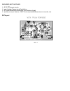
STEP-BY-STEP PC BOARD ASSEMBLY:
In all steps below, the word install means to insert the component, oriented correctly, into the right holes,
solder all wires and cut or nip away excess wire flush with the solder connection.
1. Install R1, 100 ohms (brown-black-brown).
2. Install R2, 51 ohms (green-brown-black).
3. Install C1, 4.7 or 5 pF.
4. Install C2, .01 uF (marked .01 or 103 or 10 nF).