


9
Installation
ˆ
Installation
CHOOSING A LOCATION
You can place the phone’s base on a desk or
table, or mount it on a standard wall plate or
directly on a wall. Choose a location that is:
• near an AC outlet
• near a modular telephone line jack
• out of the way of normal activities
• away from electrical machinery, electri-
cal appliances, metal walls or filing cabi-
nets, wireless intercoms, alarms, and
room monitors
• away from other cordless phones
The base’s location affects the phone’s
range. If you have a choice of several loca-
tions, try each to see which provides the best
performance.
Cautions:
You must use a Class 2 power
source that supplies 9V DC
and delivers at least 350 mA.
Its center tip must be set to positive and
its plug must fit the phone’s
DC IN 9V
jack. The supplied adapter meets these
specifications. Using an adapter that
does not meet these specifications
could damage the phone or the adapter.
• Always connect the AC adapter to the
phone before you connect it to AC
power. When you finish, disconnect the
adapter from AC power before you dis-
connect it from the phone.
Your telephone connects directly to a modu-
lar telephone line jack. If your telephone wir-
ing does not have a modular jack, you can
update the wiring yourself using jacks and
adapters (available at your local RadioShack
store), or have the telephone company up-
date the wiring for you. You must use com-
patible modular jacks that are compliant with
Part 68 of
FCC Rules
.
Note:
The USOC number of the jack to be
installed is RJ11C (or RJ11W for a wall plate
jack).
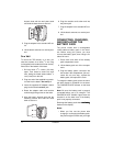
MOUNTING THE SYSTEM
On a Desk
1. Plug one end of the supplied long modu-
lar cord into the base’s
TEL LINE
jack.
2. Insert the supplied AC adapter’s barrel
plug into the base’s
DC IN 9V
jack.
3. Route the adapter’s cord through the
strain relief slot on the base.
4. Plug the modular cord’s other end into
the phone jack.
5. Plug the adapter into a standard AC out-
let.
6. Lift the base’s antenna to a vertical posi-
tion.
On a Wall Plate
1. Plug one end of the supplied short mod-
ular cord into the base’s
TEL LINE
jack.
2. Insert the supplied AC adapter’s barrel
plug into the base’s
DC IN 9V
jack.
3. Route the AC adapter and modular
cords through the grooves on the base.
4. Plug the modular cord’s other end into
the wall plate jack, then align the base’s
!