


Non-Proprietary Security Policy, Version 1.0 June 15, 2007
Polycom VSX 3000, VSX 5000, and VSX 7000s
Page 9 of 23
© 2007 Polycom, Inc. -
This document may be freely reproduced and distributed whole and intact including this Copyright Notice.
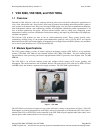
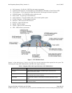
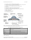
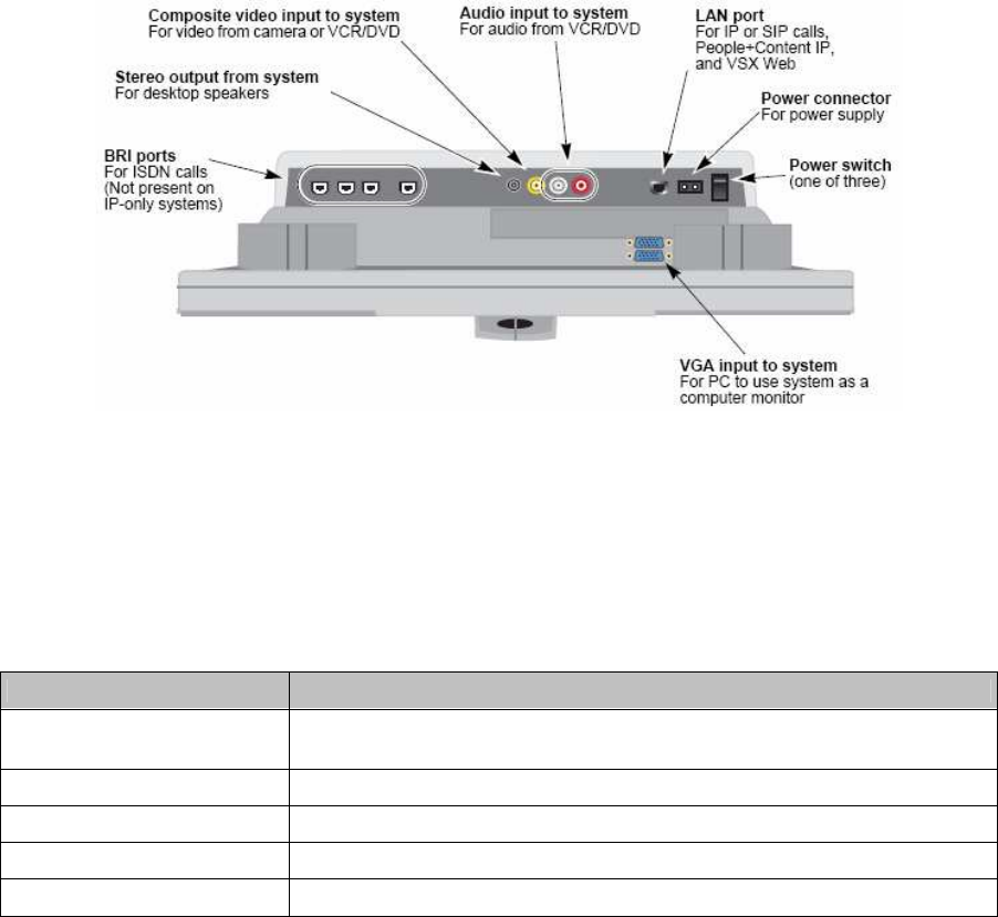
• LAN connector – For IP calls, VSX Web, and remote management
• Power connector – For power supply
• Power switch for the codec – (one of three)
• VGA connector – For Personal Computer (PC) to use system as a computer monitor and for passing the
video image from the VGA input connector to a display device
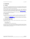
• LCD Screen – Screen for video conferencing
• IR Sensor – Input from IR sensor
• Speaker – Built-in speaker
• Camera – Input for video conferencing
• Microphone – Built-in microphone
• LED – LEDs indicate system status
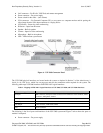
Figure 6 - VSX 3000 Connector Panel
The VSX 3000 physical interfaces are located under the system as depicted in Section 2 of the Administrator’s
Guide for the VSX Series, which lists on page one and two the connection cables required for the system. The
following table maps VSX 3000 interfaces with FIPS 140-2 logical interfaces:
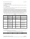
Table 2 - Mapping of FIPS 140-2 Logical Interfaces to VSX 3000, VSX 5000, and VSX 7000s Interfaces
FIPS 140-2 Logical Interface VSX 3000, VSX 5000, and VSX 7000s Port/Interface
Data Input BRI connectors, Composite video connector, LAN connector, VGA connector, Audio
Connector, Microphone, Camera
Data Output BRI connectors, Stereo connector, LAN connector, LCD Screen, Speaker
Control Input LAN connector, IR Sensor, Power switch
Status Output LAN connector, LCD Screen, LEDs
Power Power connector
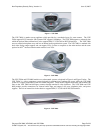
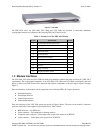
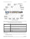
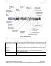
The following is the list of ports and interfaces of the VSX 5000 system and Figure 7 below shows the ports on
module’s back panel.
• Power connector – For power supply