


Non-Proprietary Security Policy, Version 1.0 June 15, 2007
Polycom VSX 3000, VSX 5000, and VSX 7000s
Page 12 of 23
© 2007 Polycom, Inc. -
This document may be freely reproduced and distributed whole and intact including this Copyright Notice.
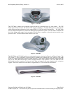
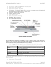
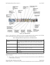
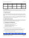
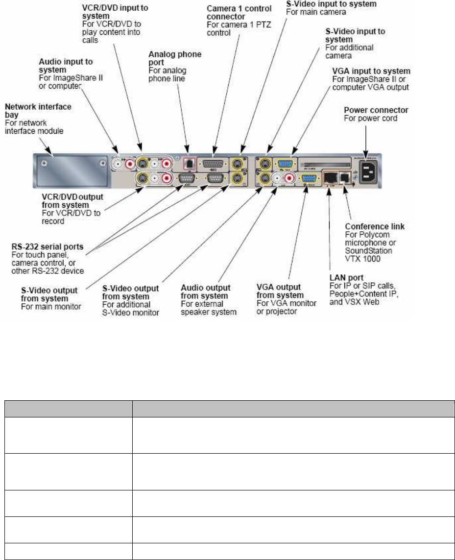
Figure 8 - VSX 7000e Back Panel
Section 1 of the Administrator’s Guide for the VSX Series lists the connection cables required for the VSX 7000e
system. The following table maps VSX 7000e interfaces with FIPS 140-2 logical interfaces.
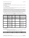
Table 4 - Mapping of FIPS 140-2 Logical Interfaces to VSX 7000e Interfaces
FIPS 140-2 Logical Interface VSX 3000, VSX 5000, and VSX 7000se Port/Interface
Data Input Network interface bay, VCR/DVD connector, Audio connector, Serial ports, S-Video
connector, Analog phone connector, VGA connector, LAN connector, Conference link
connector
Data Output Network interface bay, VCR/DVD connector, Audio connector, Serial ports, S-Video
connector, Analog phone connector, VGA connector, LAN connector, Conference link
connector
Control Input Network interface bay, Serial ports, Camera 1 control connector, LAN connector,
Conference link connector, IR Sensor, Power button
Status Output Network interface bay, Serial ports, LAN connector, Conference link connector, Power
button, LEDs
Power Power connector
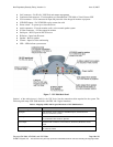
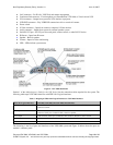
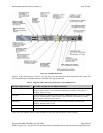
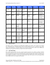
The following list provides the ports and interfaces of the VSX 7000s system and Figure 9 below shows the ports on
module’s back panel.
• Power connector – Houses power for subwoofer and optional network interface module (for BRI, PRI, and
V.35/RS-449/RS-530 connection)