


LinkPlus Interface Guide: Siemens Hicom/HiPath optiset for SpectraLink e340/h340/i640 Wireless Telephones
PN: 1725-36143-001_K.doc
10
LED emulation
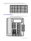
When Lines are programmed as shown on the key-map diagrams, the
numeral icons on the handset display will be mapped to the LEDs
associated with the corresponding Feature Keys. The line icons will be
displayed as follows:
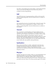
Line State optiset LED Status
Handset
Line Status Icon State
On-hook Off Off
Off-hook On On
Ringing Rates 2, 3, 5, & 6 Fast flash
On hold Rates 4 & 7 Slow flash
Feature Programming Requirements
When planning the interface, the following information must be taken
into account:
Line sequences
The handset uses two types of key sequences to access PBX features
and multiple lines. Line sequences are those where the user presses
the
LINE key and then a number key. The key-map design designates
“line” optiset E keys that should be programmed for line appearance
so that they correspond to line sequences on the handset.
The line icon on the handset will reflect activity on the corresponding
optiset E telephone key. For this reason, it is recommended that line
appearance keys on both the Hicom 150/HiPath 3000 Basic optiset E
and the Hicom 300/HiPath 4000 Standard optiset E should be used
only for line access. If only one line is assigned to a particular handset,
leave the other designated line keys identified on the key maps
unassigned on the optiset E. The handset key sequences
LINE +2 to
LINE +4 will then have no function.
Function sequences
Function sequences are those where the handset user presses the FCN
key and then a number key. Designated “function” deskset keys
programmed to system features such as Transfer and Conference may