


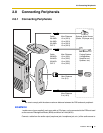
2.8 Connecting Peripherals
Installation Manual 63
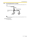
PC/Printer (via RS-232C)
A PC can be connected via the RS-232C interface and used to log and display call records, and
program the PBX. A printer can also be connected, to print call records.
Connect the PC or printer via an RS-232C cable (user-supplied).
When using special accessories such as cable, the user should use those specified in this installation
manual to comply with the limits for a Class B digital device pursuant to the FCC Rules.
Note
Use an RS-232C cross cable when connecting the PBX with a PC.
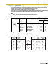
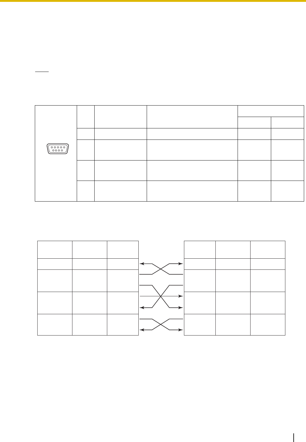
Pin Assignments
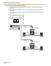
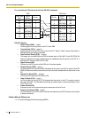
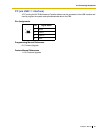
Connection Charts
For connecting a PC/printer with a 9-pin RS-232C connector
No. Signal Name Function
Circuit Type
EIA CCITT
2 RD (RXD) Receive Data BB 104
3
4
SD (TXD)
ER (DTR)
Transmit Data
Data Terminal Ready
BA
CD
103
108.2
5
6
SG
DR (DSR)
Signal Ground
Data Set Ready
AB
CC
102
107
7
8
RS (RTS)
CS (CTS)
Request To Send
Clear To Send
CA
CB
105
106
6 9
1 5
PBX PC/Printer
Circuit Type
(EIA)
Signal
Name
Pin No. Pin No.
Signal
Name
Circuit Type
(EIA)
BB RD (RXD) 2
BA SD (TXD) 3
CD ER (DTR) 4
AB SG 5
CC DR (DSR) 6
CA RS (RTS) 7
CB CS (CTS) 8
2 RD (RXD) BB
3 SD (TXD) BA
4 ER (DTR) CD
5SG AB
6 DR (DSR) CC
7 RS (RTS) CA
8 CS (CTS) CB