


Radio Disassembly - Detailed 2-9
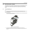
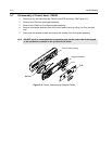
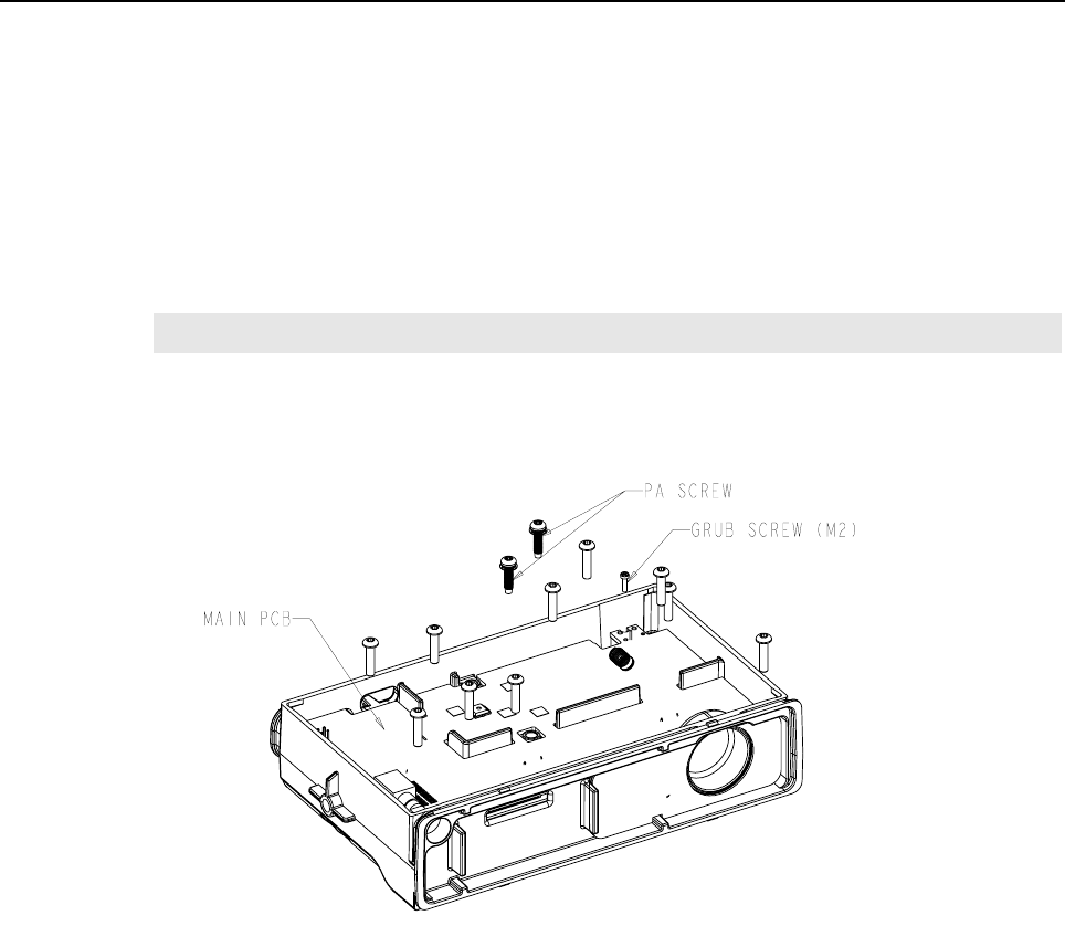
6.6 Main PCB Removal (for High Power Models)
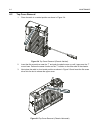
1. Remove the PA screws. See Figure 2-10.
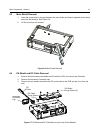
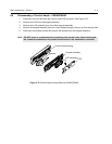
2. Remove all the screws that fix the PCB to the chassis.
3. Loosen the M2 screw (about 3 to 4 turns) on the RF connector using hex tool
(Part number: 6680334F39).
4. Loosening this screw, enables you to unscrew the RF connector from outside.
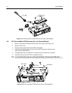
5. Carefully remove the main PCB in a diagonal manner.
Figure 2-10 PA Clip and Main PCB Removal (for High Power Models)
NOTE
It is recommended to grip the volume potentiometer and remove the PCB board