


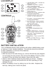
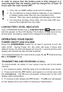


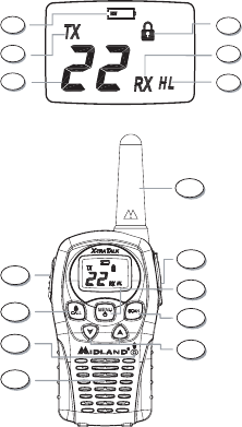
LCD DISPLAY
1. LOW BATTERY ICON – Indicates the
battery level is low.
2. TRANSMIT (TX) ICON – Indicates
radio is transmitting a signal.
3. CHANNEL NUMBER – Changes from
1~22 on GMRS/FRS band.
4. KEY LOCK ICON – Indicates KEY
LOCK mode is on.
5. RECEIVE (RX) ICON – Indicates radio
is receiving a transmission.
6. TRANSMIT POWER LEVEL ICON –
Indicates TX Power setting (H/L).
7. PTT Button – Press and hold to trans-
mit voice communication.
8. ALL/LOCK Button – Press to send a
CALL Alert signal. Press and hold to
turn KEY LOCK on/off.
9. MIC – Built-in microphone.
10. SPEAKER – Built-in speaker.
11. ANTENNA
12. EXTERNAL SPEAKER/MIC/CHG.
JACK
13. POWER / MENU Button – Press and
hold for at least 3 seconds to turn the
radio on/off. Press momentarily to
access Menu mode.
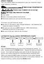
14. SCAN Button – Press to enter SCAN
mode.
15. UP▲andDOWN▼Buttons–Make
adjustments in MENU mode.
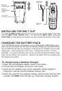
BATTERY INSTALLATION
Your LXT500/535 Series radio operates with either a NiMH battery pack
or optional 4 “AAA” alkaline batteries. The belt clip should be removed
to ease installation or removal of the batteries.
To install the batteries:
1. With the back of the radio facing you, remove the belt clip (see diagram
on next page) for easy access, then remove the Battery Cover by press-
ing down on the top center and sliding it down from the radio.
2. Insert 4 “AAA” batteries observing the polarity as shown. Installing
the batteries incorrectly will prevent the unit from operating or may
damage the unit.
3. Return the Battery Cover by sliding it up on the radio. Replace the
belt clip, making sure it locks into place.
CONTROLS
14
13
12
10
9
8
7
11
15
1
6
5
4
3
2