ADDITIONAL INSTALLATION WARNING
FAILURE TO FOLLOW THESE INSTRUCTIONS CAN CAUSE
DAMAGE TO THE TERMINAL OR CAUSE THE ASSOCIATED PBX
CIRCUIT PACK TO REMOVE POWER TO THE TERMINAL. IN
EITHER CASE THE TERMINAL WILL NOT FUNCTION CORRECTLY.
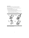
The design of this product allows it to operate on either 2-wire or
4-wire DCP circuits. In order for the terminal to function properly in either 2-wire
or 4-wire installations, there must be NO INTERCONNECTIONS between the
wire pairs used for 2-wire and 4-wire operation. Bridging or paralleling of these
pairs can result in damage to the terminal or can cause the PBX circuit pack to
remove power to the terminal.
REMOVE ALL CONNECTIONS BETWEEN PAIRS BEFORE
CONNECTING THE TERMINAL.
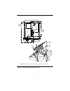
For 2-wire operation, if you need to plug the voice terminal into a
4-pin or 6-pin wall jack, instead of a standard 8-pin modular jack, refer to the
“Line Interface” table below Figure 1 in The
8400-Series Voice Terminals Instructions for Installation, Switch Administration,
and Programming the Options, 555-110-725, to insure that the wires from the 4-
pin or 6-pin wall jack are connected to the correct pins on the terminal “LINE”
jack.
4-WIRE installations MUST ONLY have PBX connections on pair 2 and pair 3
and, if necessary, auxiliary power must be connected to pair 4.
2-WIRE installations MUST ONLY have PBX connections on
pair 1 and, if necessary, auxiliary power must be connected to
pair 4.
All of this information applies to all 8400 series voice terminals, the
CALLMASTER III, and the 302B1 and 302C1 Attendant Console.


