


16
220777 C IMAGE16
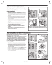
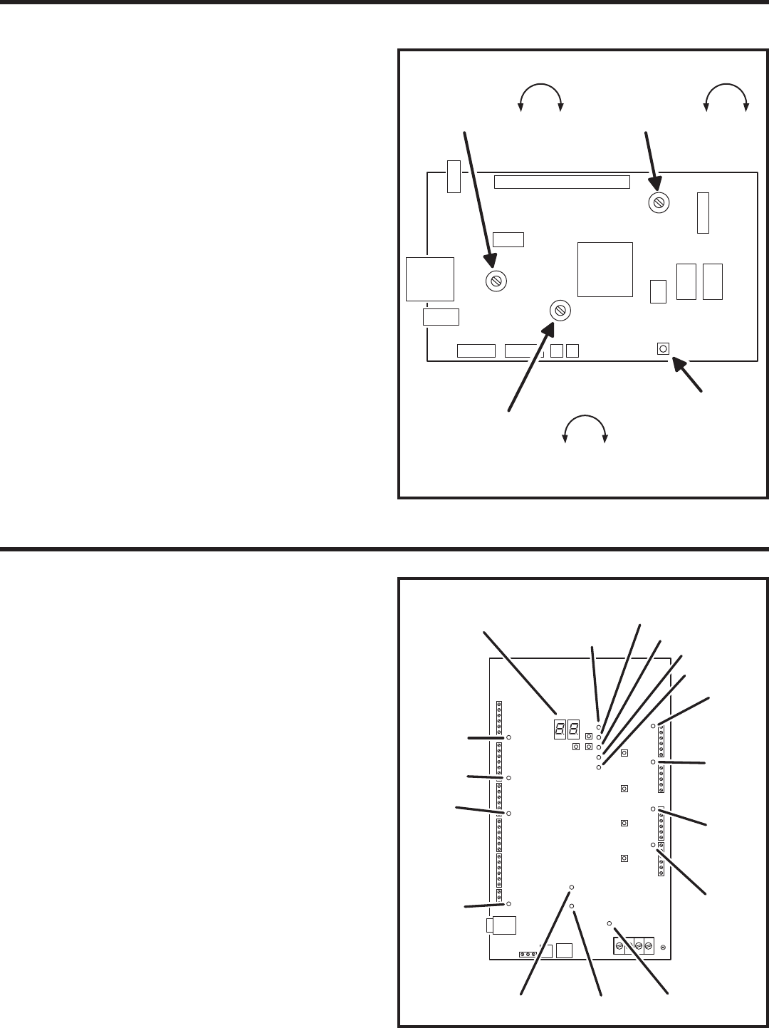
System Adjustments
The factory settings are suffi cient for most installations. The system can
be adjusted to customize the installation.
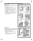
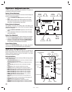
Speaker Volume Adjustment
If the resident’s voice from the speaker is too loud or not loud enough, the
speaker’s volume can be adjusted.
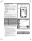
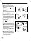
1. Locate the SPEAKER VOLUME adjustment on the CPU circuit
board.
2. Make a directory number call to test the speaker volume. While
listening to the resident’s voice, turn the adjustment clockwise for
more volume, counterclockwise for less volume.
Display Contrast Adjustment
If the lighting in the area or the viewing angle of the display in the
installation causes the display to look too dark or too light, the display’s
contrast can be adjusted.
1. Locate the DISPLAY CONTRAST adjustment on the CPU circuit
board.
2. Turn the adjustment clockwise and counterclockwise until display
has the best visibility.
System Tone Adjustment
The sound level of the tones that the system produces can be adjusted.
1. Locate the TONE VOLUME adjustment on the CPU circuit board.
2. Press keys on the keypad while adjusting the TONE VOLUME until
the tones are at the desired level. Turn the adjustment clockwise
for more volume, counterclockwise for less volume.
System Restart Button
Pressing the SYSTEM RESTART button will reboot the system’s
microcontroller. NO SYSTEM INFORMATION WILL BE ERASED.
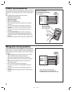
System Diagnostics
Several components on the main circuit board are for monitoring the
system during operation. When calling for technical assistance, Linear’s
Technical Services Department may ask the installer to use these
components to diagnose the system.
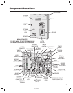
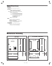
On-board Indicators
17 LED indicators are on the main circuit board. Refer to the fi gure for the
location of each indicator.
• STATUS/PROGRAM DISPLAY shows supervisory and status conditions,
also used for some local programming.
• ACCESS GRANTED lights when a credential is validated and access is
granted.
• HOST ON-LINE lights when the Host PC is connected to the Master
Node.
• VALIDATE lights when a credential is determined to be valid.
• DECODE lights when a credential has been successfully decoded.
• RADIO fl ashes when data or interference is received by the built-in radio.
• RELAY “A” ACTIVE lights when the Channel “A” relay is energized.
• RELAY “B” ACTIVE lights when the Channel “B” relay is energized.
• RELAY “C” ACTIVE lights when the Channel “C” relay is energized.
• RELAY “D” ACTIVE lights when the Channel “D” relay is energized.
• POWER lights when AC or DC power is present.
• OFF-HOOK lights when the system has the incoming telephone line
seized.
• TALK lights when the system is communicating over the telephone line.
• NETWORK fl ashes in response to network traffi c.
• PBUS blinks when any PBUS device is successively decoded.
• READER “B” fl ashes when Wiegand B device is successively decoded.
• READER “A” fl ashes when Wiegand A device is successively decoded.
AE-1000
CPU CIRCUIT BOARD
SPEAKER
VOLUME
ADJUSTMENT
MORE
LESS
DISPLAY
CONTRAST
ADJUSTMENT
TONE
VOLUME
ADJUSTMENT
MORE
LESS
MORE
LESS
SYSTEM
RESTART
BUTTON
ACCESS
GRANTED
AE-1000 MAIN
CIRCUIT BOARD
STATUS/PROGRAM
DISPLAY
HOST
ON-LINE
VALIDATE
DECODE
RADIO
RELAY "A"
ACTIVE
RELAY "D"
ACTIVE
RELAY "C"
ACTIVE
RELAY "B"
ACTIVE
POWEROFF HOOKTALK
NETWORK
PBUS
READER "B"
READER "A"