


8 EchoLink
66 CONTENTS TM-D710A/E
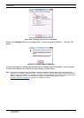
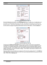
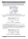
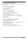
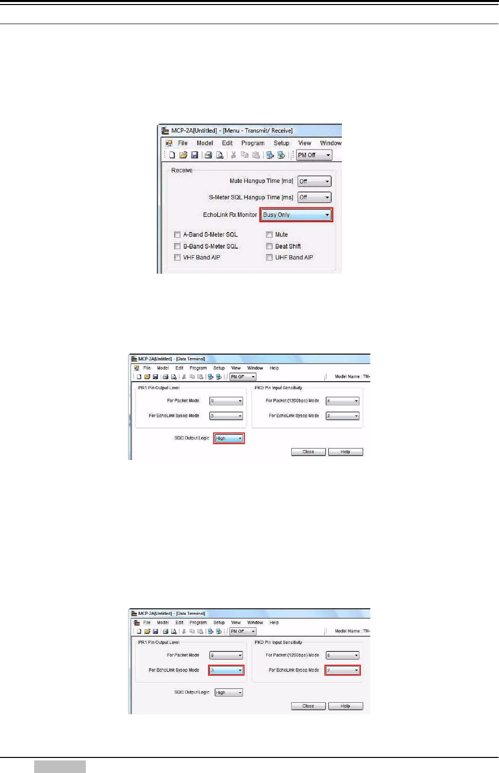
3. Select “Menu” > “Transmit/Receive” from the Edit pulldown menu. When using CTCSS or DCS
for the purpose of preventing extraneous signals or noise from being fed into the Internet from a
link station, configure “EchoLink RX Monitor” for “Busy Only” in the dropdown list. When
EchoLink Sysop mode is used, all signals received on the data band are output from the
speaker regardless whether CTCSS or DCS has matched; whereas, only those signals that
match CTCSS or DCS are output from the data terminal.
Figure 8-45 MCP-2A Transmit/Receive Window: EchoLink RX Monitor
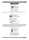
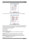
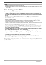
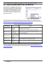
4. Select “Data Terminal” from the Edit pulldown menu. Configure “SQC Output Logic” for “High”
in the dropdown list so that a false Busy state is never detected, even when the transceiver is
turned OFF.
Figure 8-46 MCP-2A Data Terminal Window: SQC Output Logic
Note: In the Sysop Setup window in EchoLink software, do not check the Invert Sense checkbox in the RX Ctrl tab.
Refer to 8.5.2 Configuring EchoLink Software for a Link Station.
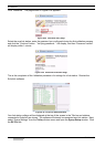
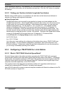
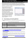
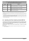
5. Select “Data Terminal” from the Edit pulldown menu. If the audio level adjustment range on
your computer is not sufficient, configure “PR1 Pin Output Level” to adjust the AF output level to
the computer. Also, configure “PKD Pin Input Level” to adjust AF input sensitivity that will vary
the AF signal level fed into the transceiver. These levels can be varied using steps of
approximately 6 dB.
Figure 8-47 MCP-2A Data Terminal Window: AF Level Adjustments