


TK-3180
46
C287
C275
C250 C228 C292
C214
FM IF
SYSTEM
C636 C666 C698
AQUA
Q207
Q206 Q205
XF200
IC200
FM IF
SYSTEM
IC200
IC600
IC606
1
6
CN601
IC607
AQUA
IC607
IC605
IC609
500mW
IC605 IC608
IC605 IC600
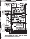
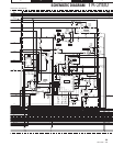
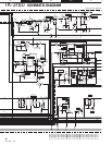
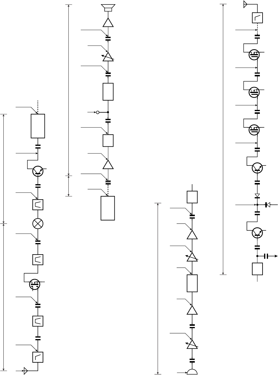
–119.0dBm –119.0dBm –114.5dBm –106.5dBm –117.5dBm –102.5dBm 239mVrms
218mVrms
383mVrms
383mVrms 409mVrms 20mVrms
381mVrms 110mVrms239mVrms
RF (Center frequency)
RF (Center frequency)
IF1 (59.85MHz)
IF2
(455kHz)
AF (1kHz)
AF (1kHz)
C728 C685
C43
C66
D205
C67
C71 C101
C107
VCO
VCO
PLL RXLO
Q13 Q100
D100
Q101
Q102
Q105
C113
C125
C149
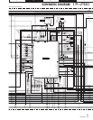
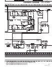
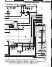
12.5mVrms
(at MIC terminal)
12.1mVrms
46.3mVrms 250mVrms
103mVrms 263mVrms
282mVrms
15.2dBm16.4dBm12.5dBm7.0dBm3.3dBm
5.0W
To make measurements in the AF section, connect the AC level meter.
(ANT input : –53dB, 1kHz FM, 3kHz DEV (Wide))
In the RF section, use a 1000pF coupling capacitor.
(The display shows the SSG input value required to obtain
12dB SINAD without local level.)
AG is set to the MIC input becomes 3kHz DEV
at 1kHz MOD (Wide).
To make measurements in the AF section,
connect the AC level meter.
In the RF section, use a 1000pF coupling capacitor.
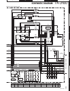
Receiver Section
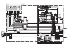
Transmitter Section
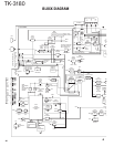
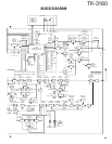
LEVEL DIAGRAM