


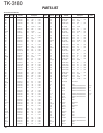
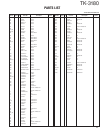
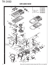
TK-3180
18
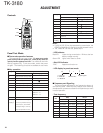
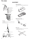
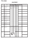
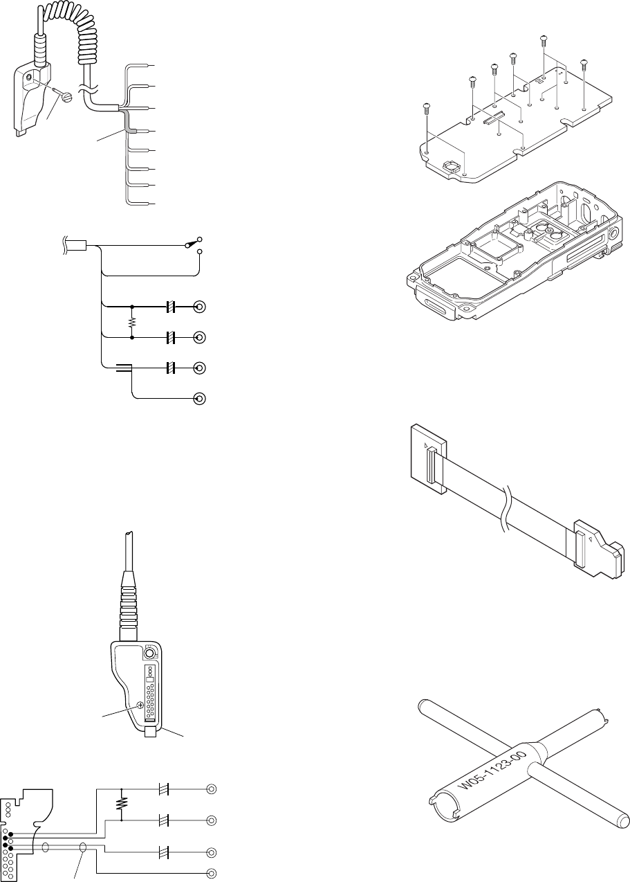
Connector case
KPG-36
Remove the
screw
PCB layout
Shield
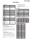
AF voltmeter
Audio generator
100µ 10 V
100µ 10 V
10µ 10 V
+
+
+
8Ω
11: GREEN (5M)
TUBE
SCREW
8: YELLOW (PF SW)
2: RED (RX AF OUTPUT)
3: BLACK (RX AF OUTPUT)
10: BROWN (GND)
6: BROWN (MIC GND)
5: WHITE (MIC INPUT)
7: BLUE (PTT SW) GND → ON
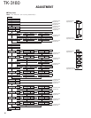
RED (2)
BLK (3)
+
+
100µ 10V
100µ 10V
8Ω
WHT
(5)
BRN (6)
BLU (7)
BRN (10)
PTT SWTo Radio
AF Voltmeter
Audio generator
+
10µ 10V
• Panel tuning
• PC tuning
Connect the wires to the PCB in the connector case of
interface cable.
For output the wires out of the connector case, need to
process the connector case.
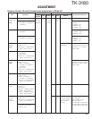
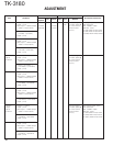
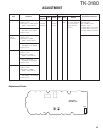
ADJUSTMENT
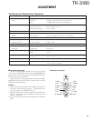
to transceiver
to VGS-1
■ Check Jig for the VGS-1
KENWOOD part No. : W05-1127-00
■ Nut wrench
In order to turn the volume nut and the channel selector
nut, use a recommendation tool.
KENWOOD part No. : W05-1123-00
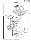
■ Repair jig (Chassis)
Use jig (part No. : A10-4077-04) for repairing the trans-
ceiver. Place the TX-RX unit on the jig and fit it with 14
screws.