


TK-3180
17
ADJUSTMENT
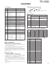
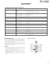
Test Equipment Required for Alignment
Test Equipment Major Specifications
1. Standard Signal Generator Frequency Range 400 to 520MHz
(SSG) Modulation Frequency modulation and external modulation
Output –127dBm/0.1µV to greater than –47dBm/1mV
2. Power Meter Input Impedance 50Ω
Operation Frequency 400 to 520MHz or more
Measurement Capability Vicinity of 10W
3. Deviation Meter Frequency Range 400 to 520MHz
4. Digital Volt Meter Measuring Range 10mV to 10V DC
(DVM) Input Impedance High input impedance for minimum circuit loading
5. Oscilloscope DC through 30MHz
6. High Sensitivity Frequency Range 10Hz to 1000MHz
Frequency Counter Frequency Stability 0.2ppm or less
7. Ammeter 5A
8. AF Volt Meter Frequency Range 50Hz to 10kHz
(AF VTVM) Voltage Range 1mV to 10V
9. Audio Generator (AG) Frequency Range 50Hz to 5kHz or more
Output 0 to 1V
10. Distortion Meter Capability 3% or less at 1kHz
Input Level 50mV to 10Vrms
11. 8Ω Dummy Load Approx. 8Ω, 3W
12. Regulated Power Supply 5V to 10V, approx. 5A
Useful if ammeter equipped
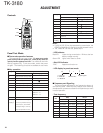
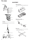
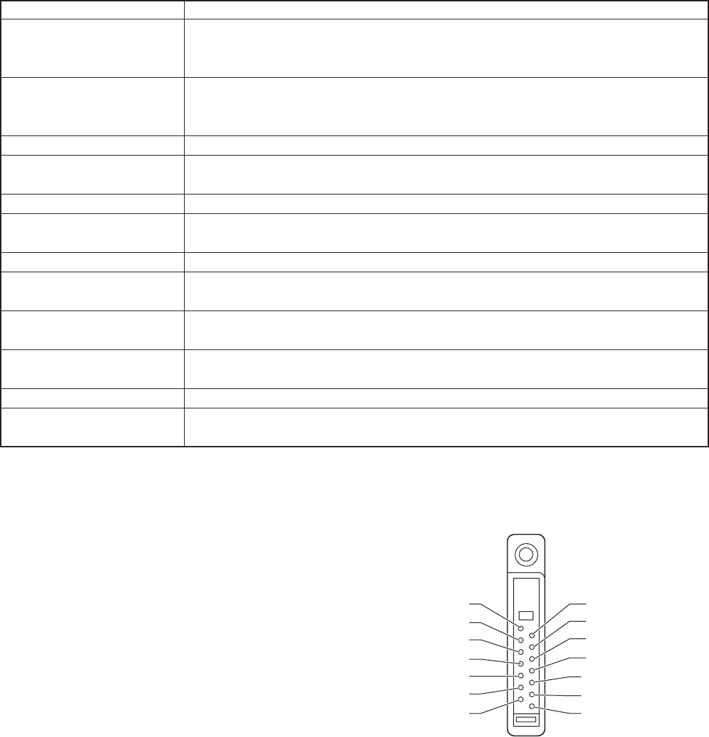
■ Universal connector
Use the interface cable (KPG-36) for PC tuning or the lead
wire with plug (E30-3287-18) and screw (N08-0535-08) for
panel tuning. Connect the plug to the universal connector of
the radio and tighten the screw.
The lead wire with plug (E30-3287-18) and screw (N08-
0535-08) terminals are as follows. Numbers are universal
connector terminal numbers.
Caution
1. When connecting the plug to the universal connector of
the radio, a short circuit may occur. To prevent this, be
sure to turn the radio POWER switch off.
2. Since the RX AF output is a BTL output, there is a DC com-
ponent. Isolate this with a capacitor or transformer as
shown in the figure.
3. Do not connect an instrument between red or black and
GND.
1: SSW
3: SP–
5: EMC
7: PTT
9: OPT
11: 5U
13: RXD
2: SP+
4: MSW
6: ME
8: PF
10: E
12: TXD
14: NC
• Universal connector