


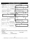
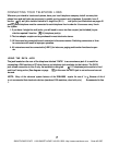
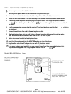

CONNECTING YOUR TELEPHONE LINES
Wherever you intend to locate each phone, have your local telephone company install as many tele-
phone lines and wall jacks as necessary to enable you to connect each telephone. If possible, have 2
two-line
(RJ
14) wall jacks installed instead of 4 single-line (RJ I I)
wall jacks (see illustrations on pages I8
and
19).
Each telephone must be connected to each telephone line in order for it to access every line in
the system.
I. If you have 4 single-line wall jacks, you will need to use a two line coupler (not included) to pro-
vide the required 2 two-line
(Rj
14) telephone jack(s).
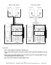
2. The two adapter coupler can be purchased in most electronic stores.
3. All lines must be connected to each extension in the same manner. Switching connectors or lines
to connectors will result in improper operation.
4. All extensions must be connected to [LINE I] for intercom, paging and transfer functions to oper-
ate.
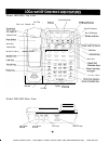
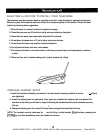
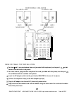
USING THE DATA JACK
The jack located on the rear of the telephone labeled “DATA” is a convenience jack. It is useful for
connecting a FAX machine or PC when there is no telephone jack available for that device. The DATA
jack allows connection to Line 2 only. An installation using two
RJ
I I C telephone jacks results in Line I
and Line 3 being active (See diagram on page
18).
In this case the DATA jack is not active and can not
be used.
NOTE:
Many of the advanced system features of the
IBM-4900
require the use
of
line
I.
Because of this it
is not recommended
that electronic devices (modems, FAX machines, door bells, etc.)
Be
connected to line
I.
I7
SMARTHOME.COM™ 1-800-SMART-HOME 949-221-9200 http://www.smarthome.com Order #5125C