


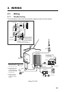
2-1
2. WIRING
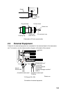
2.1 Wiring
2.1.1 Standard wiring
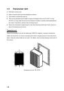
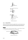
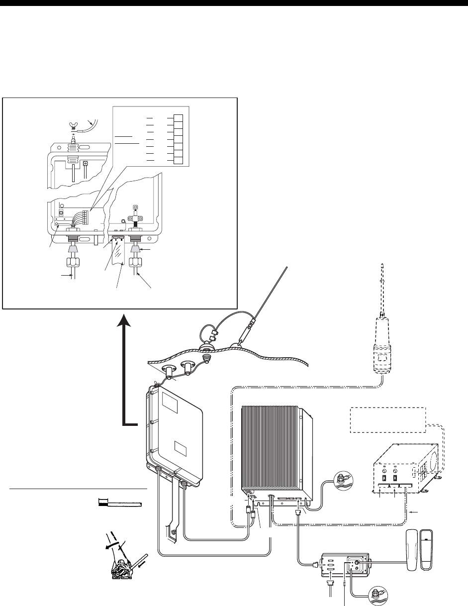
For further details, refer to the interconnection diagram at the end of this manual.
100V 10A
220V 5A
20A
ON
OFF
AC IN
LNG
+
-
+
-
DC OUT
24V
ON
OFF
+
-
DC IN
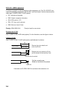
FS-2571C
FS-1570T
Local supply
Local supply
AT-1560-15
FAX-5
PR-300
AC IN
Printer
Speaker
Ground Wire
Ground Wire
DC IN
CONTROLLER
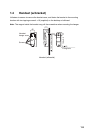
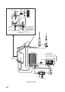
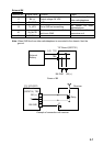
1
D.ANT(W/R
1)
T/R ANT
HS-2003
TB3
TB1
TB2
-
1
TB-2*
2
3
4
5
6
7
1 ANT
BRN
TUNE OK
RED
THROUGH
ORG
TUNE
YEL
DUMMY
GRN
+ 15V
WHT
0V
BLU
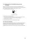
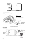
Replace this rubber sleeve
with one supplied with
accessories if using a coax
cable whose diameter is
larger than supplied one.
Signal cable
Coaxial cable
Ground
terminal
Connect to ground
to prevent interference and electrical shock.
Ground
drain wire.
To ANTENNA
Power status
monitor PSM-01
(Resin type)
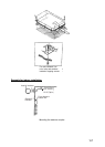
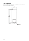
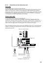
*: How to Use Terminal Opener at TB-2
1. Remove the end of
each core by 5-6 mm.
2. As shown in the figure,
set the opener in a
terminal. While pulling
the opener downward,
insert the core.
3. Release the opener.
Tug on the core to
confirm it is inserted
properly.
5~6mm
A
terminal
opener
core
Wiring (FS-1570)