


Thermometer
Replaceable Parts
15
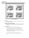
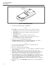
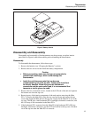
5. Push the Isothermal PCA and the Main PCA together so that the Isothermal PCA
pins go deeper into the Main PCA sockets. This holds the IR Lens in place and
allows the Main PCA to be reinstalled into the top case.
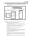
Reinstalling the Main PCA
1. While holding the IR Lens to the Main PCA, turn the Main PCA over so that the
components are facing up.
2. Align the screw holes in the Main PCA with those in the top case.
3. Align the backlight pins with the Main PCA sockets.
4. Align the Main PCA holes with the backlight posts.
5. Gently push the Main PCA down into the top case, making sure that the IR Lens goes
into the groove on the LCD-end of the top case. If it does not fit together easily,
check to make sure that everything is properly lined up and try again.
6. Reinsert and tighten the two pca screws.
To complete the thermometer reassembly, screw the bottom case to the top case, reinstall
the batteries and screw the battery compartment shut.
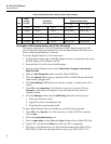
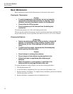
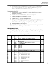
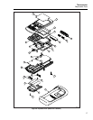
Replaceable Parts
Refer to Table 4 for all replacement part numbers and Figure 6 for part locations. Unless
specified in the “Model Number” column, all parts are for all units. To order replaceable
parts, see the “Service Centers” section of this manual.
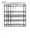
Table 4. Replaceable Parts
Item
Number Qty.
Fluke Part
Number Description
Model
Number
1 3 376756 BATTERY, PRIMARY, 1.5V, 0-150MA, AA ALKALINE All
2 4 803582 SCREW , PH, P, CAPT, STL, 4-40, .25 All
BATTERY DOOR:
3 1 642931 • SCREW, PH, P, AM THD FORM, STL, 4-14, .312 All
4 1 669838 • DOOR, BATTERY All
51
669812
669804
669801
669796
CASE, TOP
CASE, TOP
CASE, TOP
CASE, TOP
51
52
53
54
6 1 1541901 ISOTHERMAL PCA (TESTED) All
7 2 804713 CONNECTOR, ELASTOMERIC, LCD TO PWB, 2.210 L All
8A-F 1 1541895 BOTTOM CASE ASSEMBLY
Bottom Case Assembly contains:
All
8A 2 666435 • BATTERY CONTACT, DUAL All
8B 1 674744 • BATTERY CONTACT (POS) All
8C 1 674770 • BATTERY CONTACT (NEG) All
8D 1 669819 • CASE, BOTTOM All
8E 1 658689 • KEYPAD, CALIBRATION All
8F 1 675009 • SHIELD All