Thermometer
Disassembly and Reassembly
13
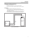
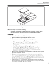
zb01f.eps
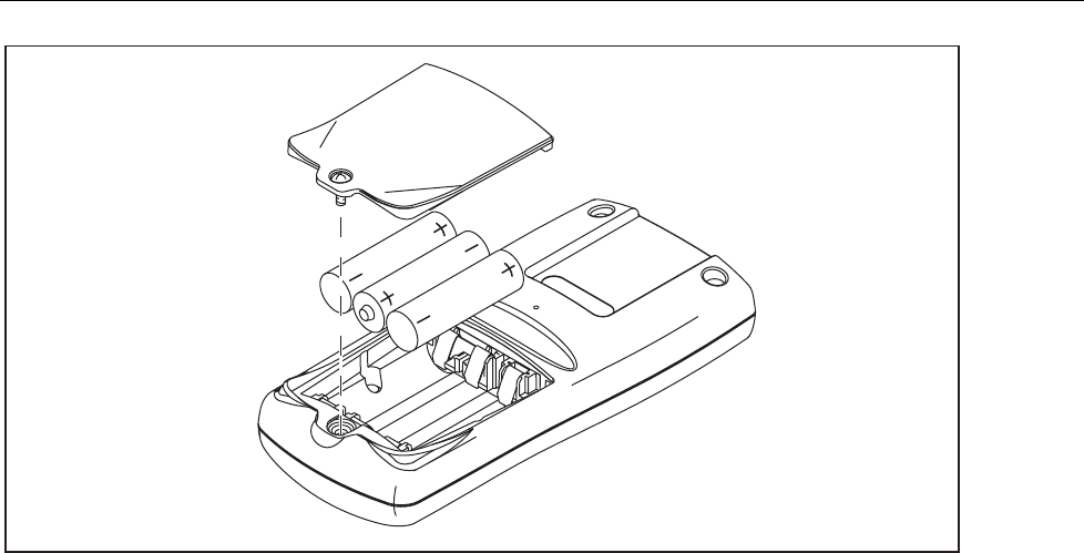
Figure 5. Battery Access
Disassembly and Reassembly
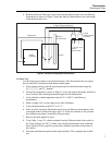
Disassembly and reassembly of the thermometer may be necessary to replace interior
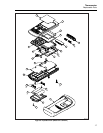
parts. Refer to Figure 6 when disassembling and reassembling the thermometer.
Disassembly
To disassemble the thermometer, follow these steps:
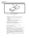
1. Remove the batteries (see “Changing the Batteries” section).
2. Remove the two screws located inside the battery compartment.
Caution
• Before proceeding, make sure that you are grounded to
prevent static discharge, which could damage the
thermometer.
• Inside the unit there are parts that can become
contaminated by oils from the skin. These parts should not
be directly handled. When lifting out the elastomeric
connectors and the main switch pad, it is recommended that
tweezers or sterile gloves be used.
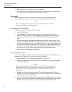
3. Remove the two case bottom screws, located at the LCD-end of the unit and separate
the bottom case from the top case.
4. Removing any of the interior components of the unit requires removing the Main
PCA. To remove the Main PCA, place the top case face down and remove the two
screws that attach the Main PCA to the top case. Gently lift the Main PCA out of the
top case. The IR Lens, small Isothermal PCA, backlight, elastomeric connectors, and
the LCD may all lift out attached to the Main PCA.
5. If the Isothermal PCA separates from the Main PCA, the Isothermal PCA, IR Lens,
backlight, elastomeric connectors, and the LCD will still be in the top case. Lift them
out of the top case after the Main PCA is removed.


