CIRCUIT DESCRIPTION
3-2
February 2001
Part No. 001-9800-001
Flash EPROM and also EEPROM U102. This infor-
mation is programmed when data is downloaded to the
transceiver by the programming software described in
Section 4.
A second microcontroller (U2) on the display
board controls the front panel display and tri-color
indicator and also detects the option switch, Select
switch, and microphone on/off hook state. Control
information is exchanged between U101 and this
microcontroller via a serial bus. The use of a second
microcontroller minimizes the number of interconnec-
tions that are required between the audio/logic and
display boards. The operating program for this micro-
controller is permanently stored on the chip and cannot
be changed.
3.1.5 RECEIVER
The receiver is a double conversion type with the
following intermediate frequencies:
UHF Models - 45 MHz and 450 kHz
800 MHz Models - 52.950 MHz and 450 kHz
900 MHz Models - 45 MHz and 450 kHz
Two bandpass filters in the front end attenuate the
image, half IF, injection, and other frequencies outside
the selected receive band. Receiver selectivity is
enhanced by a four-pole crystal filter and two 450 kHz
ceramic filters.
3.1.6 TRANSMITTER
The transmitter amplifies the synthesizer signal to
produce a power output of up to either 25 or 40 watts
(UHF) or 15 or 30 watts (800/900 MHz) at the antenna
jack. Frequency modulation of the transmit signal is
performed by modulating the synthesizer TCXO and
VCO frequencies. A control circuit senses forward
power to maintain constant power output. It also
senses final amplifier current and cuts back power if it
becomes excessive.
The use of a digital potentiometer allows the
power output to be set from the front panel when the
test mode is selected and also allows two different
power levels to be programmed for each system. The
microcontroller also monitors power amplifier
ambient temperature and voltage and cuts back power
or disables the transmitter if either are excessive.
3.2 POWER DISTRIBUTION AND SWITCHING
3.2.1 POWER SWITCHING CONTROL
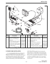
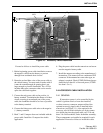
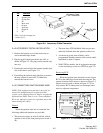
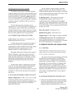
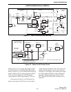
A diagram of the power distribution and
switching circuits is shown in Figure 3-1. The main
power switching is performed on the RF board by
Q510 and other transistors. This switch is controlled
by the front panel power switch, the ignition sense
input, and the microcontroller as shown in Figure 3-2.
For the front panel on-off switch to be detected, Q109
must be turned on by a high signal applied through
R170 or from the ignition switch. R170 is installed if
the ignition switch is not used to control power. Q107
and Q108 provide power switch on and ignition on
signals to the microcontroller so that it can sense those
conditions.
Q110 allows the microcontroller to hold power
on for a time after it has been turned off by the power
or ignition switch. For example, when the microcon-
troller senses that power was switched off by the front
panel switch, it holds power on for a short time so that
switch settings can be saved to memory. It also holds
power on when a power-off delay is used. Once power
turns off, power is also removed from the microcon-
troller. Therefore, power can be turned on only by the
power and ignition switches.
NOTE: The front panel power switch is a push on,
push off type (pressing it toggles between open and
closed). It is not a momentary switch.
3.2.2 SUPPLY SWITCHING
When power is turned on by the front panel
power switch, the base of Q514 on the RF board is
grounded through the power switch. Q514 then turns
on which also turns on the Darlington amplifier
formed by Q511 and Q512. These transistors are
turned on by a 13.6-volt signal applied through R535.
Series-pass transistor Q510 is then turned on and 13
volts appears on its collector. The diodes in CR505
and CR506 become forward biased only if the 8-volt
supply applied to the collector of Q514 becomes
shorted. This provides current limiting which prevents
damage to the transistors.
Q513 controls the Q511 base current in order to
maintain approximately a 0.8-volt drop across the
emitter and collector of Q510. This provides noise
POWER DISTRIBUTION (ALL MODELS)


