


CIRCUIT DESCRIPTION
3-15
February 2001
Part No. 001-9800-001
Operation
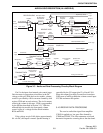
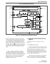
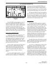
As stated in Section 3.7.1, the fR input to the
main phase detector is 50 kHz for all channels (either
6.25 or 10 kHz channel spacing). The 14.850 MHz
reference oscillator frequency is divided by 297 to
produce this signal. Fractional-N division with modulo
5 or 8 selection allows the loop frequency to be 5 or 8
times the channel spacing. Modulo 8 is used to allow
6.25 kHz (12.5 kHz) channel spacing.
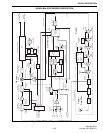
The fV input is produced by dividing down the
VCO frequency applied to the RF IN input. The first
divider is a prescaler which is a special counter
capable of operating at relatively high frequencies.
This counter divides by 64 and 65 in this application.
This divides a signal in the 400 MHz range down to
approximately 6 MHz. For each main divider output
pulse, the prescaler divides by 65 for a certain number
of pulses and then 64 for an additional number of
pulses. The number counted in each mode is deter-
mined by the programming of the “N” and “A” divide
numbers. The basic operation is as follows:
The main divider begins counting down from the
“A” number. Then when zero is reached, it begins
counting down from the “N” number until zero is
reached. The cycle then repeats. While it is counting
down the “A” number, the prescaler divides by 65, and
while it is counting down the “N” number, it divides
by 64.
To illustrate the operation of these dividers, an
example will be used. Assume a transmit frequency of
450.750 MHz is selected. Since the VCO oscillates on
the transmit frequency in the transmit mode, this is the
frequency that must be produced by the VCO. To
produce this frequency, the “N” and “A” divide
numbers are programmed as follows:
N = 83 A = 55
To determine the overall divide number of the
prescaler and main divider, the number of input pulses
required to produce one main divider output pulse can
be determined. Although the programmed “N” number
is 83 in this example, the divide number is always two
higher (85) because of reset cycles and other effects.
Therefore, the prescaler divides by 65 for 55 x 65 or
3575 input pulses. It then divides by 64 for 85 x 64 or
5440 input pulses. The overall divide number K is
therefore 3575 + 5440 or 9015. The VCO frequency of
450.750 MHz divided by 9015 equals 50 kHz which is
the fR input to the phase detector.
If the VCO frequency is not evenly divisible by
50 kHz, there is also a fractional-N number
programmed that provides the required fractional
divide number. Refer to the 800/900 MHz description
in Section 3.10.6 for more information.
NOTE: The formulas for calculating the N and A
divide numbers are described in Section 4.3.5.
3.7.6 LOCK DETECT
When the synthesizer is locked on frequency, the
LOCK output of U804 (pin 18) is a logic high voltage.
Then when the synthesizer is unlocked, this voltage is
low. A locked condition exists when the phase differ-
ence at the TCXO input is less than one cycle.
3.7.7 CHARGE PUMP
The charge pump circuit in U804 charges and
discharges C833-C836 in the loop filter to produce the
VCO control voltage. Resistors connected to the RN
and RF pins set the charge current. The RF pin resis-
tance is set by a digitally controlled potentiometer in
U802. This resistance changes with the frequency
band in order to minimize fractional-N spurious
signals. The loop filter provides low-pass filtering
which controls synthesizer stability and lockup time
and suppresses the loop reference frequency (50 kHz).
3.7.8 SHIFT REGISTER (U800, U801) AND
DIGITAL POTENTIOMETER (U802)
PROGRAMMING
Shift register U800 functions as an I/O port
expander, and shift register U801 functions as a D/A
converter to provide a 256-step output voltage for
adjusting transmitter power. In addition, the Q7 output
of U801 provides the transmit/receive signal. U802
contains four digitally controlled potentiometers that
are also adjustable in 256 steps.
These devices are cascaded together on the serial
bus so that data is shifted out of one device into
UHF SYNTHESIZER DESCRIPTION