


INSTALLATION
2-5
February 2001
Part No. 001-9800-001
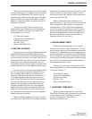
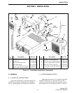
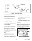
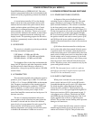
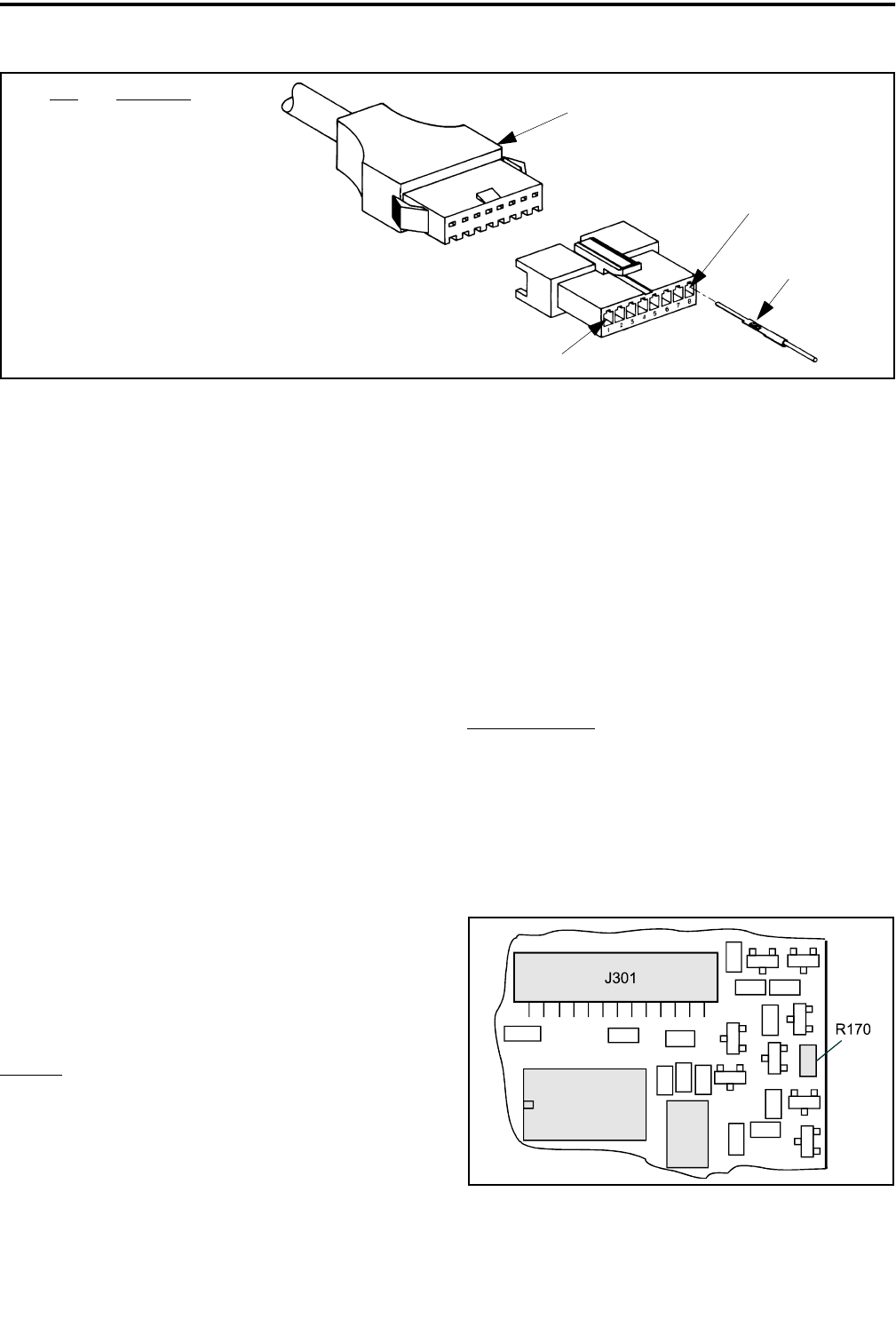
Figure 2-4 Accessory Cable Connector
Accessory Cable
From Transceiver
Pin 8
Pin 1
Insert Pin With
Tang Up
Pin Function
1 Speaker Out*
2 Sw Bat Out
3NC
4 Horn Alert
5 Ground
6Ign Sense
7Output D
8NC
* This is a low level output (see
Section 2.4.5)
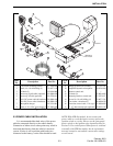
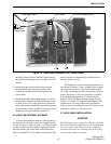
2.4.2 ACCESSORY PIGTAIL INSTALLATION
1. Remove the bottom cover of the transceiver to
access the audio/logic board.
2. Plug the pigtail cable from the kit into J101 as
shown in Figure 2-3. The plug can be inserted only
one way.
3. Position the strain relief in the external speaker jack
slot of the chassis (see Figure 2-3).
4. If installing the ignition sense function, proceed to
the next section to remove R170. Otherwise,
reinstall the bottom cover.
2.4.3 CONNECTING IGNITION SENSE WIRE
NOTE: If the ignition sense function is not used, no
transceiver modifications are required and this
section can be skipped. However, then be sure that the
Ignition Sense Delay Time is set to “Forever/Infinite”.
If it is not, improper transceiver operation may result
when starting the vehicle.
General
When the ignition sense line is connected, the
following additional functions are provided:
• The transceiver turns on and off with the vehicle
ignition switch (if the front panel power switch is
on).
• The horn alert (LTR-Net/Multi-Net) may be auto-
matically disabled when the ignition switch is on.
• A transceiver power turn-off delay can be
programmed. Standby current (receive mode, audio
squelched) is about 1 ampere.
• With LTR-Net models, the de-registration message
is sent and settings saved (see NOTE on page 2-3).
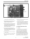
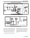
Removing R170
When the ignition sense function is used, resistor
R170 on the audio/logic board must be removed. The
general location of this resistor is shown in Figure 2-3,
and the exact location is shown in Figure 2-5. Care-
fully remove R170, taking care not to damage board
traces or adjacent components.
Figure 2-5 R170 Location Diagram