


CIRCUIT DESCRIPTION
3-3
February 2001
Part No. 001-9800-001
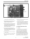
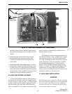
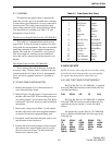
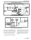
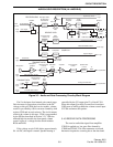
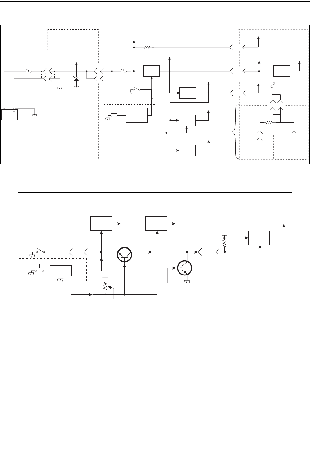
Figure 3-1 Power Distribution and Switching
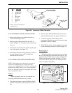
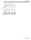
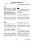
Figure 3-2 Power On-Off Control Circuit
+
Chassis
Ground
Vehicle
Battery
15A
Fuse
Power
Cable
Power Amplifier
Board
Transceiver
Power
Connector
CR600
Transient
Suppressor
Unsw Bat
Unsw Bat
Sw Bat
Unsw Bat
J600
J201
1
2
11
J501
J302
F500
4A
Q510
Switch
Front Panel
On-Off Sw
U501
U105
8V
Regulator
5V
Regulator
8V
5.5V
Regulator
8VTx
Switch
U502
Q504
5.5V
8VTx
From Shift
Reg U801
From Latch
U112 A/L Bd
Sw Bat
2
5
15
Sw Bat
8V
Vcc
12
J100
J3
Sw Bat
Sw Bat
Sw Bat
J2 J1
2
5
J1
Microphone
Jack
Display Board
Interface
Board
Audio/Logic
Board
RF Board
R533
F100
2A
R2
HighTier
On-Off Sw
On-Off
Latch
(A/L Bd)
LowTier
4
10
11
High
Tier Only
Front Panel
On-Off Sw
20 18
J3 J302
J100
J201
Q107 Q108
Power Switch
Sense
Ignition On
Sense
To uC,
Pin 60
To uC,
Pin 62
Q110
Power Hold
From Shift Reg
U111, Q7
Unsw Bat
Unsw Bat
R170
From Ignition
Switch
This Resistor Installed If
Ignition Sense Not Connected
Q510
Supply
Switching
Circuit
Interface Board
(High Tier Only)
Audio/Logic Board RF Board
Q109
Sw Bat
Note: Arrows Indicate Signal Flow.
U113A-D
Power On-Off Latch
LowTier Only
51
filtering of the 13.6-volt supply. The emitter of Q513
is biased at about 4.5 volts by R538 and R542 (with a
battery voltage of 13.6 volts). CR504 mirrors the base-
emitter voltage of Q513, and the voltage across R541
is the same as the voltage across R542 when the
voltage applied to R536 is approximately 12.8 volts.
Noise pulses less than 1.6 volt P-P then do not
appear on the output of Q510 because of the emitter
voltage filtering provided by C565. This reduces the
amount of noise applied to circuits powered by the
switched 13.6-volt supply such as audio power ampli-
fier U306. Additional filtering of the switched and
unswitched battery supplies is provided by C548-
C553. Resistor R534 turns Q514 off when power is
turned off.
POWER DISTRIBUTION (ALL MODELS)