


DTI 2000 Manual e EDITED.doc 8
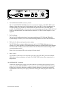
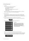
Use one of the TO PAGING MANAGER sockets (not both simultaneously) for connecting the
DTI 2000 to the DPM 4000. The DTI 2000 needs to be connected to a paging console input (DPC
IN, RJ-45 socket) of the DPM 4000 using the supplied, 3.5m long interface cable (RJ-12 to RJ-
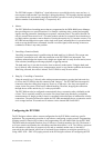
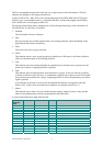
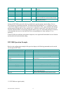
45). The following diagrams show the pin-assignment of sockets and cables. The LED labelled
DATA is located next to the sockets. This LED lights during active data transmission between
DTI 2000 and DPM 4000 System Manager providing indication of a correct connection.
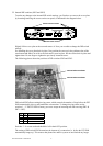
TO PAGING MANAGER connector’s pin-assignment
Interface cable RJ-12 / RJ-45
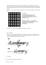
4.2 Connecting Phone Lines or a Telephone set
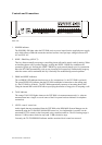
Two phone connectors are located on the rear panel of the DTI 2000. Connect the PHONE LINE
socket with the telephone wall outlet. The LOOP THRU socket provides a connection facility for
an optional telephone set.
NOTE: The LOOP THRU signal is disconnected whenever the DTI 2000 picks up a phone call via
the PHONE LINE socket.
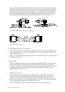
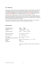
4.3 Power Supply
Insert the supplied power supply unit’s round plug into the POWER SUPPLY socket on the rear
panel of the DTI 2000. Turn the plug’s safety lock clockwise to establish a securely locked
connection. Afterwards, connect the supplied mains cord to the power supply unit before inserting
the mains plug into the mains wall outlet. The DTI 2000 is immediately operational upon
establishing accurate connection.
5. Adjusting the Audio Level
Adjusting the level of the audio signal that is transmitted to the DPM 4000 System Manager is
possible via the LEVEL TO PAGING MANAGER trimmer. Doing so, use a small, flat
screwdriver to first set the trimmer to its centre position. Call the DTI 2000 and speak with a
normal voice into the receiver while adjusting the audio signal level for best transmission quality.
The level meter should not indicate any signals in the red area.
The TO TELEPHONE indicator and the corresponding control are not currently used.