


DTI 2000 Manual e EDITED.doc 4
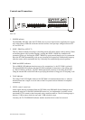
Rear
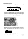
6. TO PAGING MANAGER connectors, female
The two TO PAGING MANAGER connectors represent the interface to the DPM 4000 System
Manager. Using either the 9-pole D-Sub connector or the 6-pole RJ-12 socket (simultaneous use
of both terminals is not possible) to establish audio and data connection to the DPM 4000 is
possible. The DTI 2000 needs to be connected to one of the paging console inputs (DPC IN, RJ-45
socket) on the DPM 4000. The needed interface cable (RJ-12 to RJ-45) with a length of 3.5m is
supplied.
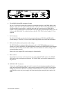
7. DATA indicator
The DATA LED indicates that data is being transmitted between DTI 2000 and DPM 4000
System Manager. Therefore, it serves as main monitoring indicator for correct data connections.
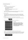
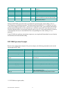
8. DIP switch for address and operation mode settings
The DTI 2000 allows setting an address between 1 and 16. CAUTION: Make sure never to
connect two or more appliances with identical address settings to the DPM 4000 System Manager,
since this would inevitably result in data conflicts. This also includes the address settings of the
connected paging consoles.
Please refer to the chapter DIP-switch settings for further details.
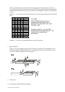
9. Phone sockets
Two telephone connectors are located on the rear panel of the DTI 2000. Connect the PHONE
LINE socket with your telephone wall outlet. The LOOP THRU socket offers connection for a
telephone set.
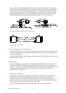
10. POWER SUPPLY connector
Connect the supplied power supply unit to this connector by inserting the round plug of power
supply unit into the POWER SUPPLY socket on the rear panel of the DTI 2000. Turn the plug’s
locking ring in clockwise direction to establish a reliable connection. Afterwards, connect the
supplied mains cord to the power supply unit before inserting the mains plug into a mains wall
outlet.