


DTI 2000 Manual e EDITED.doc 5
Se Up and Connections
1. Unpacking
The DTI 2000 package contains the following parts:
1 DTI 2000 Digital Telephone Interface
1 power supply unit, 100 – 240V AC
1 IEC mains cord
1 interface cable for DPM 4000 connection, RJ-12 to RJ-45
1 telephone cable, RJ-11 to TAE
1 owner’s manual
Make sure that everything is complete and that nothing is damaged. Otherwise, immediately
contact your dealer or the TELEX / EVI Audio service department.
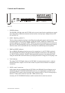
2. DIP switch settings
The DTI 2000 provides a single DIP-switch on the rear panel and two internal DIP-switches.
Theses switches are meant for making specific basic settings, which have to be made before
operating the appliance for the first time. Generally, no changes need to be made during the later
operation.
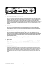
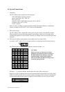
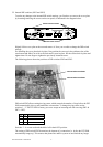
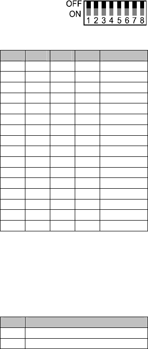
2.1 DIP switch for address and operation mode settings on the rear panel (S201)
A switch is “OFF” when it is set to its upper position. Consequently the ON-position is down.
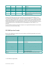
The following table shows how to set addresses using the switches 1 – 4:
SW1 SW2 SW3 SW4 ADDRESS
OFF OFF OFF OFF 1
ON OFF OFF OFF 2
OFF ON OFF OFF 3
ON ON OFF OFF 4
OFF OFF ON OFF 5
ON OFF ON OFF 6
OFF ON ON OFF 7
ON ON ON OFF 8
OFF OFF OFF ON 9
ON OFF OFF ON 10
OFF ON OFF ON 11
ON ON OFF ON 12
OFF OFF ON ON 13
ON OFF ON ON 14
OFF ON ON ON 15
ON ON ON ON 16
CAUTION:
Make sure never to connect two or more
appliances with identical address settings to
the DPM 4000 System Manager, since this
would inevitably result in data conflicts.
This also includes the address settings of the
connected paging consoles.
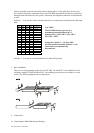
Switches 5 – 7 provide no function and should be left in their OFF-position (up).
Switch 8 serves for switching between normal operation and download mode. Leave this switch
(SW8) in its OFF-position (up) for normal operation. Download mode is meant for updating the
software and loading country-specific settings by DYNACORD or one of its service centers.
SW8 DTI 2000 MODE
OFF Normal
ON Download