


1
2
3
4
5
6
7
8
9
10
11
12
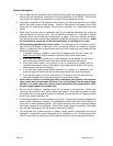
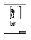
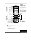
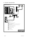
To Line
Interface or
Relay Board
Incoming Central Office
Phone Lines - 12 Max
Outgoing Phone Lines
to Apartments
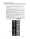
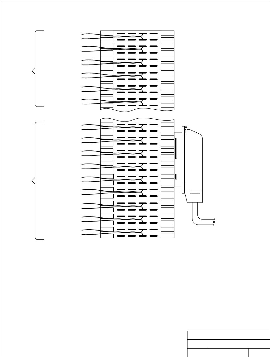
Line 1 TIP - Pin 1
Line 1 RING - Pin 2
Line 2 TIP - Pin 3
Line 2 RING - Pin 4
Line 3 TIP - Pin 5
Line 3 RING - Pin 6
Line 4 TIP - Pin 7
Line 4 RING - Pin 8
Line 5 TIP - Pin 9
Line 5 RING - Pin 10
Line 6 TIP - Pin 11
Line 6 RING - Pin 12
Line 4 TIP - Pin 33
Line 4 RING - Pin 34
Line 5 TIP - Pin 35
Line 5 RING - Pin 36
Line 6 TIP - Pin 37
Line 6 RING - Pin 38
33
34
35
36
37
38
Line 7 TIP - Pin 39
Line 7 RING - Pin 40
Line 8 TIP - Pin 41
Line 8 RING - Pin 42
Line 9 TIP - Pin 43
Line 9 RING - Pin 44
39
40
41
42
43
44
Line 10 TIP - Pin 45
Line 10 RING - Pin 46
Line 11 TIP - Pin 47
Line 11 RING - Pin 48
Line 12 TIP - Pin 49
Line 12 RING - Pin 50
45
46
47
48
49
50
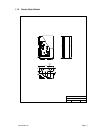
A
CB
D
IMPORTANT!
When the phone wires are
punched down on ROW B,
bridge clips from row B to row
C must be installed. If the
phone wires are punched
down on row C, bridge clips
are not required.
DOORKING, INC., INGLEWOOD, CA 90301
Date: Dwg. No.
Detail Wiring - RJ71C Phone Block
Rev.
Title:
12/06
C
M1816-065-6
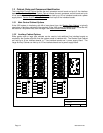
NOTE:
The RJ71C wiring configuration is not recognized
by all telephone companies.
For Bell Canada, which has jurisdiction in
Ontario and Quebec, refer to CA-79X
For BC Tel, which has jurisdiction in British
Columbia, refer to BC Tel CRTC Spec 182 B5.
IMPORTANT!
TIP (positive) RING (negative)
polarity MUST be observed.
TIP must be punched down on
the top terminal of each pair
and RING must be punched
down on the bottom terminal
of each pair.
1820-065-B-2-06 Page 13