


Telco and ISP Dial Scenarios and Configurations
Large-Scale POPs
DNC-317
Cisco IOS Dial Services Configuration Guide: Network Services
How Stacking Works
Before you install and configure a stack of access servers, you should understand the basic concepts
described in the following sections, and how they work together in a large-scale dial-in solution:
• A Typical Multilink PPP Session
• Using Multichassis Multilink PPP
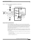
• Setting Up an Offload Server
• Using the Stack Group Bidding Protocol
• Using L2F
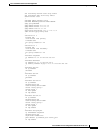
A Typical Multilink PPP Session
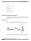
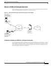
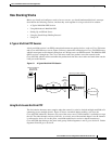
A basic multilink session is an ISDN connection between two routing devices, such as a Cisco 766 router
and a Cisco AS5200 access server. Figure 54 shows a remote PC connecting to a Cisco 766 ISDN router,
which in turn opens two B-channel connections at 128 kbps across an ISDN network. The Multilink PPP
(MLP) session is brought up. The Cisco 766 router sends four packets across the network to the
Cisco AS5200, which in turn reassembles the packets back into the correct order and sends them out the
LAN port to the Internet.
Figure 54 A Typical Multilink PPP Session
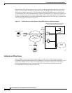
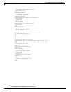
Using Multichassis Multilink PPP
The dial solution becomes more complex when the scenario is scaled to include multiple multilink calls
connecting across multiple chassis. Figure 55 shows a terminal adapter making a call in to the
Cisco AS5200, labeled #1. However, only one of the access server’s 48 B channels is available to accept
the call. The other channels are busy with calls. As a result, one of the terminal adapter’s two B channels
is redirected to device #2. At this point, a multilink multichassis session is shared between two
Cisco AS5200s that belong to the same stack group. Packet fragments A and C go to device #1. Packet
fragments B and D go to device #2.
S6752
Hunt
group
555-1001
Dial-in session #1
PC running
Windows 95
Cisco 766
ISDN network
4
4
2
2
1
1
3
3
Internet access
Service provider network
Cisco AS5200