


3-3
Cisco ATA 187 Analog Telephone Adaptor Administration Guide for SIP (Version 1.0)
OL-21862-01
Chapter 3 Installing the ATA 187
Installing the ATA 187
Installing the ATA 187
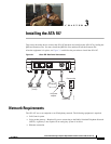
To install an ATA 187, follow these steps:
Procedure
Step 1 Connect the power supply to the Cisco DC Adapter port.
Step 2 Connect a straight-through Ethernet cable from the network to the 10/100 SW port on the ATA 187. Each
ATA 187 ships with one Ethernet cable in the box.
Note You can use either Category 3/5/5e/6 cabling for 10 Mbps connections, but you must use Category 5/5e/6
for 100 Mbps connections.
Attaching a Phone to the ATA 187
You can attach one or two phones to an ATA 187 by connecting them to a line port of the ATA 187 with
a RJ11 cable. The line LED will blink when there is activity on that line.
Verifying the ATA 187 Startup Process
After the ATA 187 has power connected to it, the phone begins its startup process by cycling through
these steps:
1. The LEDs are on.
a. Power
b. Line 1
c. Line 2
d. Set Up
The ATA 187 boots up in this step; it may take up to one minute.
2. The LEDs flash.
The ATA 187 is launching its application in this step.
3. Only the Power LED is on.
The ATA 187 is registering with Cisco Unified Communications Manager. You will hear a busy tone
when you go offhook on the phone. It can take up to one minute for this to complete.
4. All of the LEDs flash again (Optional).
If the ATA 187 flash memory is erased or the load is corrupted, all the LEDs will flash again. The
ATA
187 will download the image files and write to the flash. The ATA 187 will reboot and start from
step 1.
When you go offhook on the phone, you will see the line LED on and you will hear dial tone. The
ATA
187 has completed the startup process.