


BT Versatility
Installation and Maintenance Manual
41
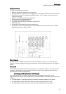
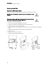
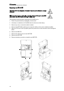
Replacing the CCU Control PCB
This PCB is NOT hot swappable. The System must be powered down to change
this board
ESD precautions must be made when replacing this board. Connect to the ESD
pillar on the CCU MDF before removing the CCU cover
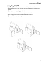
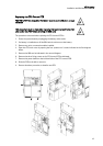
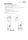
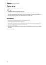
The procedure to be used when replacing the CCU control PCB is:
1. Power the system down by unplugging the battery at the mains.
2. If a battery is installed turn off the BBU switch to disconnect the battery.
3. Remove any voice or network modules installed.
4. Open the CCU main cover by opening the four ‘quarter turn’ screws indicated in the first diagram
below.
5. Remove the 008 card as indicated in the second diagram.
6. Remove the three fixing screws on the CCU control PCB as indicated.
7. Remove the power lead from the left-hand side of the CCU control PCB.
8. Slide the PCB to the left to remove it.
9. Reverse the above procedure to install a new PCB.