


Wireless Installation and Configuration Guide Page 13
IP Office [15-601082] Issue [1] (1 June 2006)
Introducing the AVPP
Overview
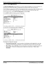
As shown in the system diagram, the AVPP is connected to the Ethernet switch. The specifications
covered here, allow for flexibility in physical placement of the components within the stated guidelines.
See the Setup and Administration Guide for your vendor's IP system, for information on LAN
requirements, network infrastructure and IP addressing.
Required Materials
The following equipment must be provided by the customer:
Power Outlet – must accept Avaya provided AC adapter.
Backboard space – the AVPP is designed to be wall mounted to ¾” plywood securely screwed
to the wall.
Screws – required to mount the AVPP to the wall. Four #8 - ¾” panhead wood screws (or similar
device) are required.
Cat. 5 Cable – RJ-45 connector at the AVPP. Connection to the Ethernet switch.
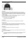
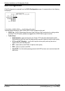
Locating the AVPP
The AVPP measures approximately 4 x 12.5 x 7 inches, and weighs about five pounds. The unit can be
wall mounted, vertically or horizontally, over ¾” plywood. The AVPP can also be rack mounted using a
rack mount kit (sold separately).
Locate the AVPP in a space with:
Sufficient backboard mounting space (for wall mount) and proximity to the LAN access device
(switched Ethernet hub) and power source.
Easy access to the front panel, which is used for cabling.
A maximum distance of 325 feet (100 meters) from the Ethernet switch.