


1-29ASUS A8V-VM
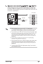
• Werecommendthatyouconnectahigh-denitionfrontpanel
audio module to this connector to avail of the motherboard high-
denitionaudiocapability.
• Ifyouwanttoconnectahigh-denitionfrontpanelaudiomoduleto
this connector, make sure the Audio Controller item in the BIOS is
set to [Enabled]. See page 2-22 for details.
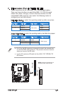
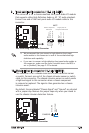
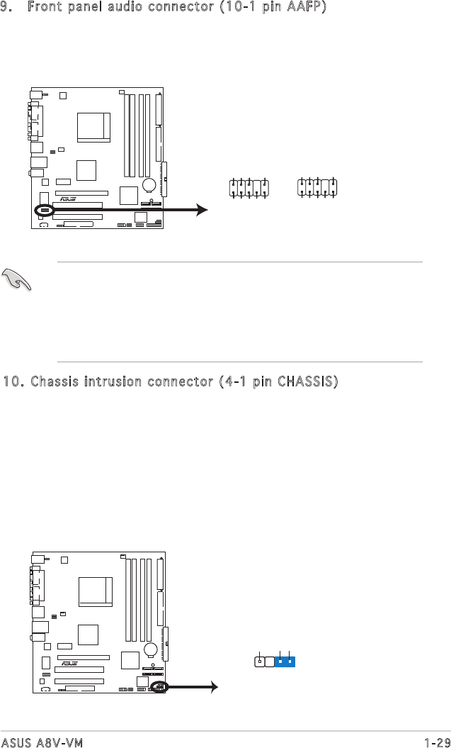
9. Front panel audio connector (10-1 pin AAFP)
This connector is for a chassis-mounted front panel audio I/O module
thatsupportseitherHighDenitionAudioorAC`97audiostandard.
Connect one end of the front panel audio I/O module cable to this
connector.
A8V-VM Analog Front Panel Connector
AAFP
Back line out L
AGND
Line out_R
Line out_L
Back line out R
NC
+5VA
+5VA
AGND
SENSE2_RETUR
PORT1 L
PORT2 R
PORT2 L
SENSE1_RETUR
SENSE_SEND
PORT1 R
PRESENCE#
GND
A8V-VM
R
Azalia compliant
definition
Legacy AC 97
compliant definition
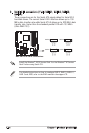
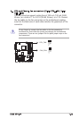
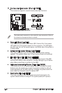
10. Chassis intrusion connector (4-1 pin CHASSIS)
This connector is for a chassis-mounted intrusion detection sensor
or switch. Connect one end of the chassis intrusion sensor or switch
cable to this connector. The chassis intrusion sensor or switch sends
a high-level signal to this connector when a chassis component
is removed or replaced. The signal is then generated as a chassis
intrusion event.
By default, the pins labeled “Chassis Signal” and “Ground” are shorted
with a jumper cap. Remove the jumper caps only when you intend to
use the chassis intrusion detection feature.
A8V-VM Chassis Intrusion Connector
A8V
-
VM
R
CHASSIS
+5VSB_MB
Chassis Signal
GND
(Default)