


1-22 Chapter 1: Product introduction
1.10.2 Internal conne ctors
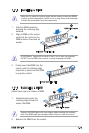
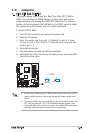
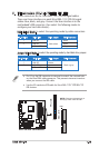
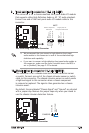
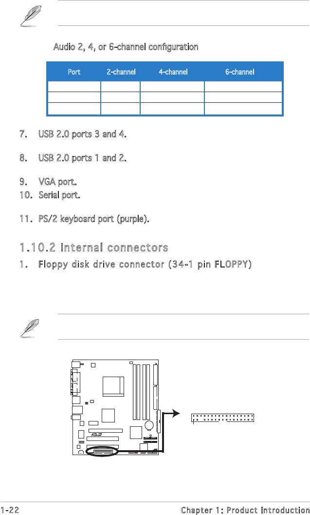
1. Floppy disk drive connector (34-1 pin FLOPPY)
Thisconnectorisfortheprovidedoppydiskdrive(FDD)signalcable.
Insert one end of the cable to this connector, then connect the other
endtothesignalconnectoratthebackoftheoppydiskdrive.
Pin 5 on the connector is removed to prevent incorrect cable connection
when using a FDD cable with a covered Pin 5.
A8V-VM Floppy Disk Drive Connector
A8V-VM
R
NOTE: Orient the red markings on
the floppy ribbon cable to PIN 1.
PIN 1
FLOPPY
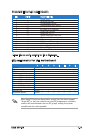
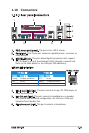
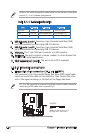
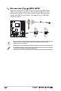
Refertotheaudiocongurationtablebelowforthefunctionoftheaudio
portsin2,4,or6-channelconguration.
Audio2,4,or6-channelconguration
Light Blue Line In Back Surround Back Surround
Lime Line Out Front Speaker Out Front Speaker Out
Pink Mic In Mic In Center/Base
Port 2-channel 4-channel 6-channel
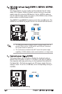
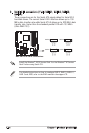
7. USB 2.0 ports 3 and 4. These two 4-pin Universal Serial Bus (USB)
ports are available for connecting USB 2.0 devices.
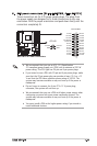
8. USB 2.0 ports 1 and 2. These two 4-pin Universal Serial Bus (USB)
ports are available for connecting USB 2.0 devices.
9. VGA port. This 15-pin VGA port connects to a VGA monitor.
10. Serial port. This port connects a mouse, modem, or other devices that
conformwithserialspecication.
11. PS/2 keyboard port (purple). This port is for a PS/2 keyboard.