21
■
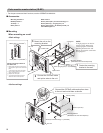
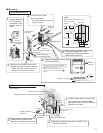
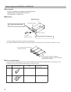
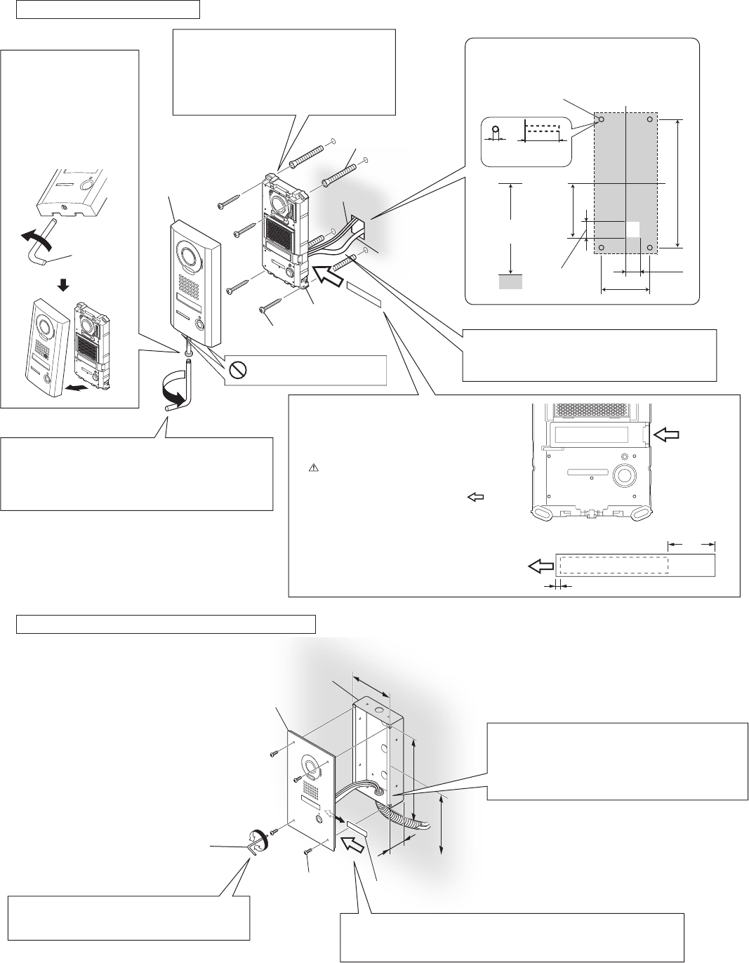
Mounting
IS-DV (surface-mount)
ABCDEFG
IS-DVF (fl ush-mount), IS-SS (fl ush-mount)
e.g.) IS-DVF
Special
screwdriver
(included)
Loosen
Tighten
Vandal-resistant
front panel
81 mm (3-1/4'')
194 mm (7-11/16'')
Water escape holes
Do not block the holes.
Ø 6 mm
(Ø 1/4")
35 mm
(1-3/8")
Anchor x 4
(included)
Screw mounting
hole x 4
To insertion opening
To
insertion
opening
NOTE
Make room for threading a screw.
1
Peel off the protective seals on the plate (both sides).
2
Fill in the name on the transparent name plate.
Be sure to leave 25 mm (1") of white space on the
right end to account for insertion.
3
Insert the fi lled-in transparent name plate at the
specifi ed insertion opening (indicated with
in
diagram).
2 mm (1/8")
25 mm
(1")
Mounting height
GL=1,500 mm (5')
Tighten
Special screw x 4
(included)
Vandal-resistant front panel with the unit attached
Flush mount back box (included)
Transparent name plate
45 mm
(1-13/16'')
120 mm
(4-3/4'')
235 mm
(9-5/16'')
90 mm (3-9/16")
25 mm (1")
25 mm (1")
Unit center
Unit
center
The unit
Screw (for wall-mounting) × 4
(included)
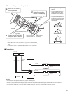
Loosen the screw
1
with the special
screwdriver, and
remove the front
panel.
Insert the transparent name plate.
2
(IS-DV and IS-DVF)
Open the terminal cover, and
3
connect the CAT5e/6 cable and
option wires to the unit.
Fasten the unit to the
4
mounting surface.
Use board anchors or concrete
*
plugs as needed.
Attach the front panel to the unit by
5
hanging the upper 2 parts on the unit.
Tighten the screw with the lower part of
*
the front panel pressed to the wall.
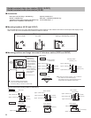
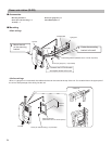
Mounting height (box center)
GL=1,500 mm (5')
Loosen
Special screwdriver
(included)
Install the back box in the wall, and
1
then connect the CAT5e/6 cable
and option wires to the unit with the
terminal cover open.
Insert the transparent name plate. (IS-DVF only)
2
See above for details.
*
Fasten the front panel to the
3
back box with the special screws.
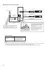
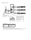
Option wires
CAT5e/6 cable


