


17
■
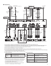
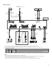
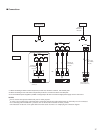
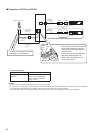
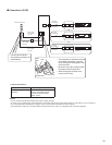
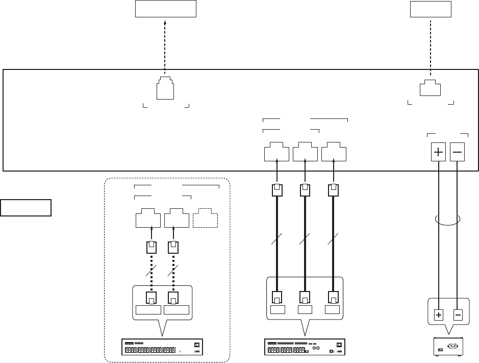
Connections
IP1 IP2 IP3
LAN
IS-RCU
IS-CCU
DC48V
ETHERNET
CO
TELEPHONE
10m (33')
10m (33')
15m (50')
2C
IP1 IP2 IP3
φ0.8-1.2mm
(20-16 AWG)
IP1 IP2 IP3
IS-RCU
IS-CCU
CAT5e/6 (x3)
10BASE-T
100BASE-TX
100m (330')
CX1/IP1 CX2/IP2
CAT5e/6 (x2)
P
*3
*1: When connecting a central control unit (IS-CCU) to this unit, connect it to the IP1, IP2 and IP3 ports.
*2: When connecting a room sub control unit (IS-RCU) to this unit, connect it to the IP1 and IP2 ports.
*3: Do not install two power supplies in parallel to a single input. Be sure to connect a single power supply unit to a control unit.
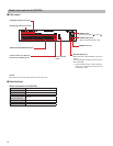
NOTES:
Do not use the unoccupied terminals and ports for other purposes.
•
In order to prevent miswiring, label both ends of each cable with the unit and terminal names to which they are to be connected.
•
For connecting other manufacturer’s products, refer to the instruction manuals for those products.
•
The illustration of the unit’s front panel differs from the actual one. This is for simplifying the connection diagram.
•
Power supply unit
(IS-PU-UL/IS-PU-S)
Central control unit
(IS-CCU) *1
Room sub control unit
(IS-RCU) *2
PBX/Telephone
(North America only)
Switch (Hub)
or
(non-shielded)
(non-shielded)
P: Polarized