


–29–
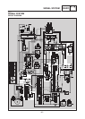
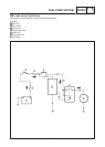
SIGNAL SYSTEM
ELEC
S Drain the fuel and remove the fuel sender
from the fuel tank.
S Disconnect the fuel sender coupler from the
wire harness.
S Connect the posket tester (Ω 1) to the fuel
sender.
S Turn the main switch to “ON” or “P”.
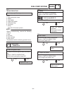
S Check for voltage (12 V) on the “Brouwn/White”
lead at the flasher relay terminal.
S Is the voltage within specification.
YES NO
Replace the flasher
relay.
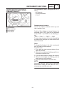
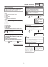
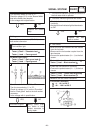
5. Voltage
S Connect the pocket tester (DC 20 V) to the
bulb socket connector.
Flasher lights
Turn indicator light
A
B
At flasher light (left):
Tester (+) lead ! Chocolate lead
Tester (–) lead ! Frame ground
1
At flasher light (right):
Tester (+) lead ! Dark green lead
Tester (–) lead ! Frame ground
2
B
A
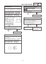
S Turn the main switch to “ON” or “P”.
S Turn the turn switch to “L” or “R”.
S Check for voltage (12 V) on the “Chocolate”
lead or “Dark green” lead at the bulb socket
connector.
S Is the voltage with in specification.
YES NO
Wiring circuit from
turn switch to bulb
socket connector is
faulty, repair.
This circuit is good.
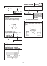
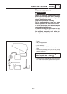
1. Fuel level indicator light bulb and socket
S Check the fuel level indicator bulb and socket
continuity.
S Are the fuel level indicator light bulb and sock-
et OK?
YES NO
Replace the bulb
and/or socket.
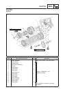
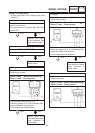
2. Fuel sender
Tester (+) lead ! Green/Red terminal
Tester (–) lead ! Black terminal
1
2
S Check the fuel sender for continuity.
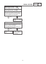
S Connect the pocket tester (Ω 1) to the fuel
sender
Tester (+) lead ! Green/Red terminal
Tester (–) lead ! Black terminal
1
3
S Measure the fuel sender resistance.
Fuel sender resistance
: 4 X 10 Ω at 20_C
: 90 X 100 Ω at 20_C
4
5
2. The fuel level indicator light fails to come on or
the fuel meter fails to operator.