


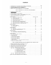

CONTENTS
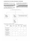
INTRODUCTION TO THE INSTALLATION MANUAL FOR EXES-6000
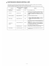
FUNCTIONS WHICH REQUIRE ADDITIONAL UNITS
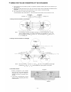
TIE-LINE CONNECTION OF THE EXCHANGES
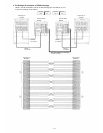
WIRING FOR TIE-LINE CONNECTION OF THE EXCHANGES
Page
2
3
5
8
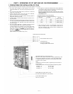
PART 1. OPERATING OF CP UNIT AND NO. 200 PROGRAMMING
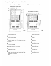
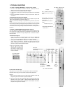
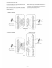
1. Precautions for Installation of CP-63
2
3. Trouble Shooting
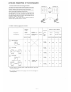
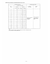
4. CP-63 DIP Switches for Function Selection
5. Dip Switch Selection and Station No. 200 Programming for Each Function
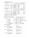
6. Function Code Table for Station No. 200 Programming
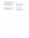
7. Station No. 200 Programming for Each Function
11
12
13
16
17
18
21
[Function Group A]
7-1 Executive Priority (Highest Priority)
7-2 Continuous Calling Tone
7-3 Stations Allowed Access to All Call
7-4
Stations Allowed Access to Conferenc
e
7-5
Automatic Access to Paging
7-6 Stations Allowed Access to One-shot Make Output
7-7 Stations Allowed Access to Make/Break Output
7-8 Stations Allowed Access to 8 Selectable or Decimal Output
7-9 Stations Allowed Access to 4 Decimal Digits Output
[Function Group B]
7-10 Secretary Transfer
7-11 Master/Sub Relationship
7-12 Group Hunting
[Function Group C]
7-13 Paging Zone
7-14 Group Blocking 1: Establishment of each Group
7-15 Calling Party Indication (Lamp Type)
[Function Group D]
7-16 Group Blocking 2: Allowing Calls among Groups
7-17 Group Blocking 3: Allowing Group Access to Paging
FUNCTION CODE
50
51
52
53
54
56
57
58
59
60
61
62
70
71
72
81
82
21
22
23
24
25
27
28
29
30
31
32
33
34
35
36
37
38
[Function Group E]
7-18 Programmable Station Numbering
8. Programming Data Table
Initial Programming
Function Table for the System
Function Table for Stations (1)
Function Table for Stations (2)
Function Table for Stations (3)
Paging Zone Table
Station Numbers Table for Calling Party Indication (Lamp Type)
Tables for Group Blocking (3 Tables)
90
39
41
41
42
43
44
45
46
46
46
PART 2. FUNCTION SELECTION FOR DATA TRANSMITTING AND RECEIVING UNITS
9. Setting of Channel Select Switch of Transmitting Unit (DT-E11)
and Word Select Switch of Receiving Unit (DR-B61)
10. DIP Switch Table for Data Transmitting and Receiving Units
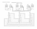
11. System Diagram of Data Transmitting and Receiving Units
12. Explanation of Data Transmitting Unit Output Channels
13. Explanation of Data Receiving Unit Output Data
13-1 CH-0 IN-OUT Annunciation (500 Contacts)
13-2 CH-1 (1) One-Shot Make Output (50 Contacts)
(2) Make/Break Output (100 Contacts)
(3) 8-Selectable Make Output (9 Units)
(4) Decimal Output (9 Units)
(5) 4 Decimal Digits Output (9 Units)
(6) Pager Control Output (64 Contacts)
13-3 CH-2 Calling Party Indication (Lamp Type) (1)
13-4 CH-3 Calling Party Indication (Lamp Type) (2)
Appendix. Instructions for building the CP-63 in the EXES-5000
49
50
51
52
53
53
54
54
54
54
54
54
55
56
57
— 1 —
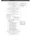
. Initial CP 63 set up