


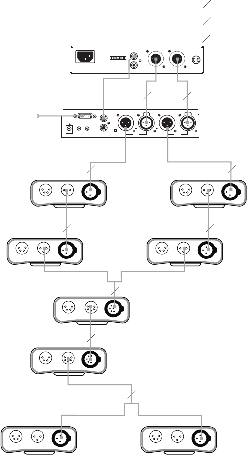
9
12-15 VDC
+
-
1
SPEAKERS
PROGRAM
INPUTS
2
LINE LEVEL
1 VRMS
P.A.
EXP
OUT
CHN 2
VOL
PGM 2
VOL
PGM 1
BAL - OUT
UNBAL - IN
PUSH PUSH
CHN 1
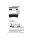
To all stations
on channel 1
Program Input
cable. From 2
audio sources
Speaker Inter-
connect cable.
To all stations
on channel 2
SPS2000A
Power Supply
Combine / Isolate Switch
set to Isolate
US2000A
Master Station
11
1
Y
Y
1
2
1
1 1-channel cable
2 2-channel cable
Y “Y” cable
1
HEADSET LINES
HEADSET LINES HEADSET LINES
HEADSET LINESHEADSET LINES
HEADSET LINES
HEADSET LINES
HEADSET LINES
BP-1000
BP-1000 BP-1000
BP-1000 BP-1000
BP-1000
BP-2000
BP-2000
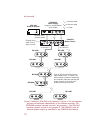
Note: A JB-2 Junction Box may be
used instead of the “Y” cables. The
JB-2 provides a means of combining
two channels, while also allowing the
single channels to be continued
directly from the junction box.
CHN 1
CHN 2
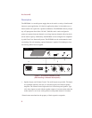
CLASS 2 WIRING 1.5A 24VDC
100-240 VAC 60/50 HZ
MADE IN USA
®
INPUT 1
SPEAKER
INPUT 2
LINE LEVEL
1 VRMS
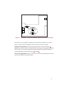
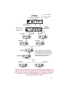
Figure 4. Typical connections using one SPS2000A Power Supply for two
intercom channels. The two program sources are monitored independently
by the intercom channels. All audio (program and intercom) is monitored as
a monaural mix in the SPS2000A speaker. The US2000A is set for
monaural speaker output (default).