


Power-Up Check
1. Plug in any DC wallpacks that are being used with individual intercom stations.
☞
If you plug in DC wallpacks after applying power to the SPS2000A, you
may get an overload indication at the SPS2000A. This is because the
stations that are being powered by wallpacks will draw current from the
SPS2000A until their own DC supplies are connected.
11
CHN 1
CHN 2
CLASS 2 WIRING 1.5A 24VDC
100-240 VAC 60/50 HZ
MADE IN USA
®
INPUT 1
SPEAKER
INPUT 2
LINE LEVEL
1 VRMS
CHN 1
CHN 2
CLASS 2 WIRING 1.5A 24VDC
100-240 VAC 60/50 HZ
MADE IN USA
®
INPUT 1
SPEAKER
INPUT 2
LINE LEVEL
1 VRMS
12-15 VDC
+
-
1
SPEAKERS
PROGRAM
INPUTS
2
LINE LEVEL
1 VRMS
P.A.
EXP
OUT
CHN 2
VOL
PGM 2
VOL
PGM 1
BAL - OUT
UNBAL - IN
PUSH PUSH
CHN 1
To ½ of stations
on channel 2
To ½ of stations
on channel 1
To ½ of stations
on channel 2
To ½ of stations
on channel 1
SPS2000A
Channel 1 Power
Combine / Isolate Switch
set to Combine
US2000A
Internal DIP
switches set
for binaural
operation
SPS2000A
Channel 2 Power
Combine / Isolate Switch
set to Combine
1
1
1
1 1 1
1
Denotes 1-channel cables
Program input
cable. From 2
audio sources
Speaker inter-
connect cables.
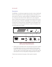
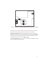
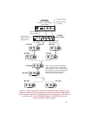
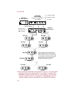
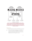
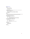
Figure 6. Using two SPS2000A Power Supplies to provide a greater
capacity on each channel. Using two SPS2000A Power Supplies also lets
you independently monitor and adjust volume for both intercom channels
without the need for a separate powered loudspeaker. In this application,
the US2000A should be set for binaural speaker output as described in the
US2000A User Manual.