


10
Audiocom®
TELEX COMMUNICATIONS, INC.
MADE IN USA
INPUT 1
INPUT 2
LINE LEVEL
1 VRMS
12-15 VDC
BAL
+
-
12-15 VDC
+
-
1
SPEAKERS
PROGRAM
INPUTS
2
LINE LEVEL
1 VRMS
P.A.
EXP
OUT
CHN 2
VOL
PGM 2
VOL
PGM 1
BAL - OUT
UNBAL - IN
PUSH PUSH
CHN 1
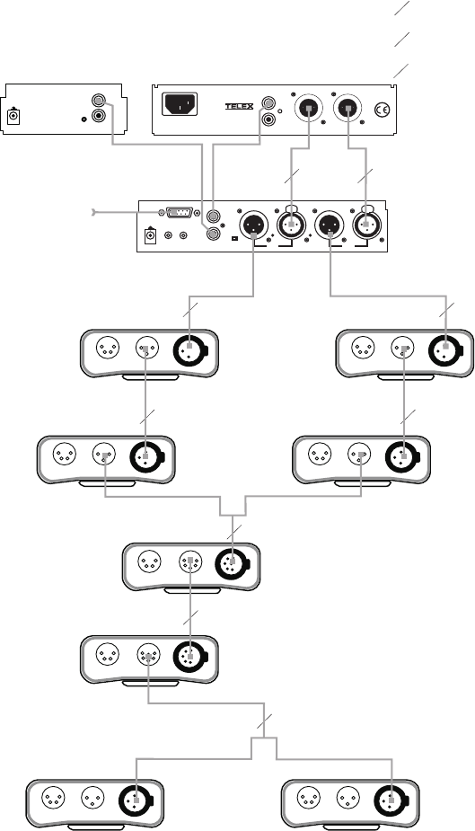
To all stations
on channel 1
Program input
cable. From 2
audio sources
Speaker inter-
connect cables.
To all stations
on channel 2
SPS2000A
Power Supply
Combine / Isolate Switch
set to Isolate
US2000A
Master Station
SPK1000
Powered Speaker
11
1
Y
Y
1
2
1
1 1-channel cable
2 2-channel cable
Y “Y” cable
1
HEADSET LINES
HEADSET LINES HEADSET LINES
HEADSET LINESHEADSET LINES
HEADSET LINES
HEADSET LINES
HEADSET LINES
BP-1000
BP-1000 BP-1000
BP-1000 BP-1000
BP-1000
BP-2000
BP-2000
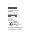
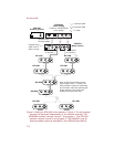
Note: A JB-2 Junction Box may be
used instead of the “Y” cables.The
JB-2 provides a means of combining
two channels, while also allowing the
single channels to be continued
directly from the junction box.
CHN 1
CHN 2
CLASS 2 WIRING 1.5A 24VDC
100-240 VAC 60/50 HZ
MADE IN USA
®
INPUT 1
SPEAKER
INPUT 2
LINE LEVEL
1 VRMS
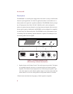
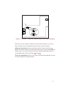
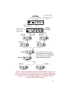
Figure 5. Adding an SPK1000 to the example in Figure 4. The two program
sources are monitored independently by the intercom channels. The
SPS2000A monitors intercom channel 1 and program 1. The SPK1000
monitors intercom channel 2 and program 2. The US2000A is set for
binaural speaker output as described in the US2000A User Manual.