SAMSUNG Installation
DCS-816 March 1999
7-5
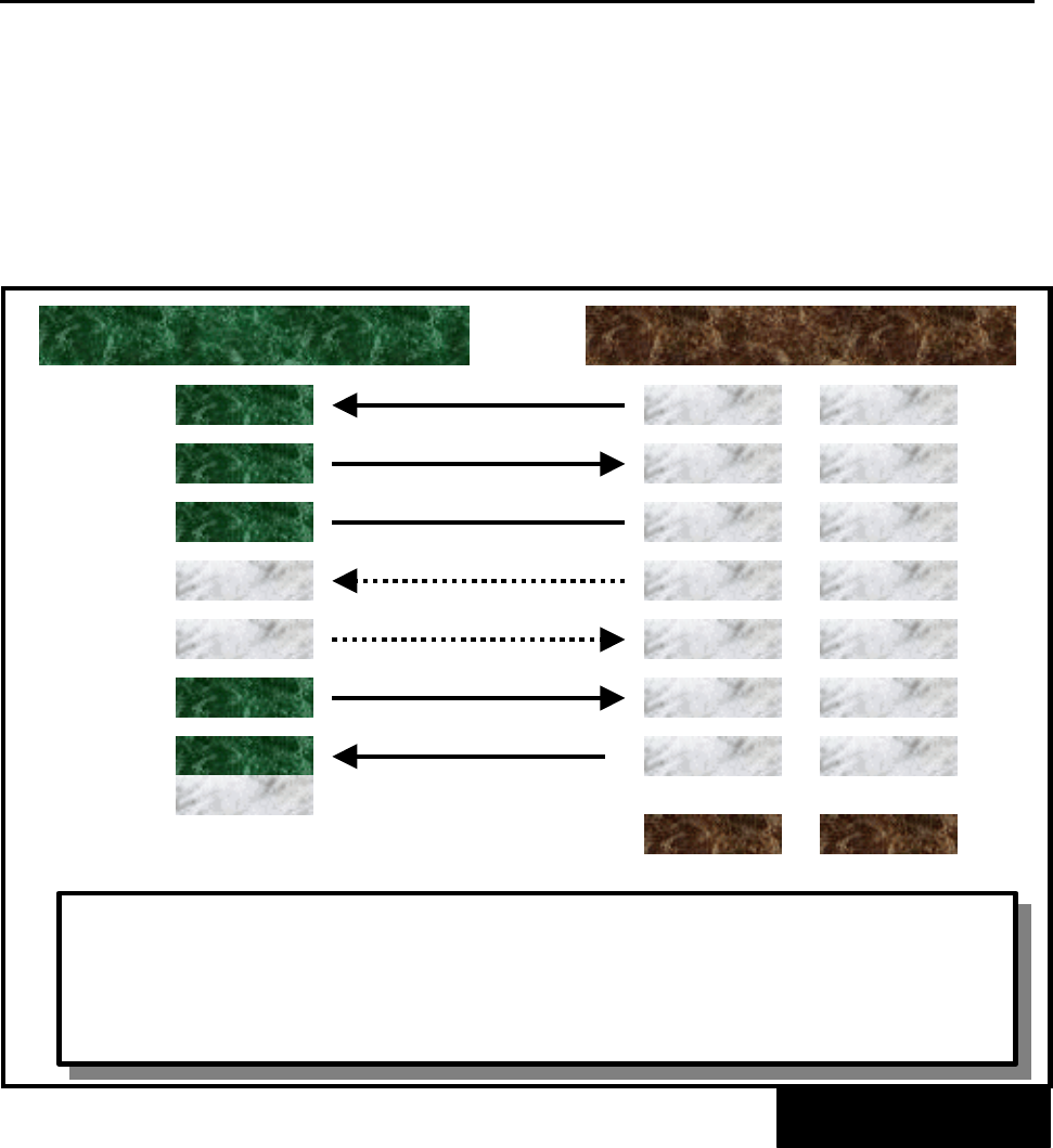
7.6 PC Programming (Figure 7-5)
To program the system via a personal computer (PC), connect a PC equipped with the proprietary
program, PCMMC, to one of the serial interface connectors (DB9) on an SIO option card (Figures
3-1 and 3-2). Before connecting the PC, ensure that the system power is turned OFF. Any
external battery, if installed, should also be removed. Otherwise, the system as well as the PC
may be severely damaged.
Use a pin-to-pin RS232C cable. Only pins 2, 3, 4, 5, and 6 are required. When the PC needs to
be more than 5 metres away from the system, shielded computer cable is required. Connect a
male DB9 connector to the SIO card and then connect a connector that meets the requirement of
the PC to the other end. The cable must not exceed 100 metres.
The signal DCD (1) and RTS (7) are optional, which means the system does not refer to the signal
status. For specific equipment, DSR (6) may not detect the DTR signal from the external source.
In this case, connect the DTR signal wire to the DCD (pin 1) of the DCS-816 serial interface.
PIN CONNECTIONS TO PC
FIGURE 7-5
SIO BOARD (DTE DB9) PC (DTE DB25 or DB9)
RXD (2)
TXD (3)
GND (5)
DCD (1)
TXD (2)
RXD (3)
GND (7)
RTS (4)
² THE SYSTEM POWER SHOULD BE REMOVED BEFORE CONNECTING THE
DEVICE
² CONNECT A PC EQUIPPED WITH PCMMC TO ONE OF THE DB9
CONNECTORS ON AN SIO OPTION BOARD
² DCD (1) MAY REPLACE DSR (6) FOR SPECIFIC EQUIPMENT
TXD (3)
RXD (2)
GND (5)
RTS (7)
DB25
DB9
RTS (7)
DTR (4)
CTS (5)
DSR (6)
CTS (8)
DSR (6)
DSR (6)
DTR (20)
DTR (4)
DCD (1)
Technical Manuals Online! - http://www.tech-man.com


