


10
2. Make sure the voltage of the power source
corresponds to the voltage of the planer as
recorded on the motor plate.
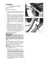
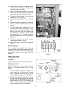
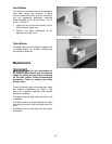
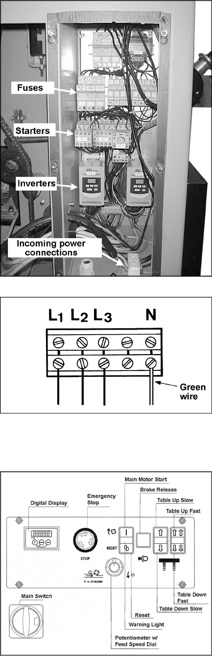
3. Open the electrical enclosure on the left
side of the machine (Figure 3) by loosening
the screws and sliding the panel upward.
4. Connect the three phases to the terminals
marked L1, L2, L3 (Figure 4).
5. Connect the green neutral wire to terminal
“N”.
6. Connect the machine to power (or install the
fuses or reset the breakers at the power
source).
7. Test the rotation of the cutterhead. Turn on
the main power switch (see Figure 5) and
then the main motor switch (Figure 5). The
pulley on the main motor (on the side near
the electrical enclosure) should rotate
counterclockwise. If it rotates clockwise,
stop the machine with the red stop button
(Figure 5 ).
8. Disconnect machine from power source,
and exchange leads L1 and L2.
9. Reconnect power, and close the electrical
cover.
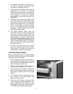
Dust Collection
It is strongly recommended this planer be
connected to a dust extraction system, via the 6”
(160mm) dust port at the rear of the planer. Your
dust collector should have at least 1500 CFM
capacity.
Adjustments
Controls
Figure 5 shows the control panel for the planer.
Starting procedure
NOTE: The planer will not start if the hood is
raised, or if the brake release light is on (see
below).
1. Turn Main Switch to position “I”. [NOTE: The
main switch has a lock-out hole, through
which a padlock or similar device can be
inserted, when the switch is in “O” position]
2. Push the Main Motor Start button; the motor
will start in Star-Delta. After a few seconds
you will hear the motor switch over to full
speed operation. NOTE: The inverters (see
Figure 3) have been factory programmed
and their settings should not be altered.
Figure 3
Figure 4
Figure 5