


Chapter 1- Hardware Description
1-8
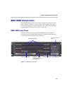
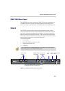
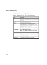
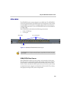
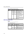
The following items appear on the RMX 2000 rear panel:
Table 1-3 RMX 2000 Rear Panel - RTM IP Component Description
Item Description
LAN 1 NA - Disconnected.
Note: LAN 1 is covered with a plastic cap that should not
be removed.
LAN 2 Used for the Network connection.
LAN 3 For Remote Access only using the Permanent
Management Network. For more information, see the
RMX 2000 Administrator’s Guide, Appendix F: "Alternate
Management Network” on page F-1.
Note: When not in use, LAN 3 is covered with a plastic
cap that should not be removed.
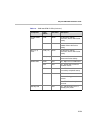
10/100 ShMG NA - For debugging purposes only.
Note: 10/100 ShMG is covered with a plastic cap that
should not be removed.
Serial NA - For debugging purposes only.
USB USB key connection. For more information, see the RMX
2000 Getting Started Guide, "First Time Installation and
Configuration” on page 2-1.
Standby button Toggle between CPU activation and standby.