


Polycom RMX 2000 Hardware Guide
1-7
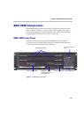
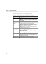
RMX 2000 Rear Panel
The RMX 2000 rear panel contains the RTM IP board and optionally, the
RTM ISDN board. In addition, the rear panel houses the main power
switch, AC inlet, a circuit breaker, and additional communications ports.
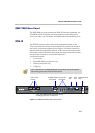
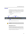
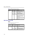
RTM IP
The RTM IP board provides system shelf management based on the
ATCA standard and connects to the backplane. It controls and monitors
fans on the system and regulates power supply. This board contains an
Ethernet Switch managing the network of the system and routing traffic.
This board routes data between the boards and components of the system,
and provides connectivity to external IP networks.
Connections include:
•3 LAN ports
• 10/100Mb ShMG port (Future Use)
• 1 Serial port (Future Use)
•1 USB port
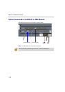
Figure 1-2 RMX 2000 RTM IP Rear Panel Layout
LAN1, LAN3 and the 10/100Mb ShMG ports shall not be used and the plastic
caps covering those ports should not be removed.
LAN 1-3 Ports
& LEDs
10/100Mb ShMG
LAN & LEDs
Internal LAN
connections
Serial
Port
USB
Port
Standby button &
LED
LAN1, LAN 3, ShMG and the Serial ports are only
for debugging and not for customer use