2.3 Installation of the Trunk Cards
Installation Manual 57
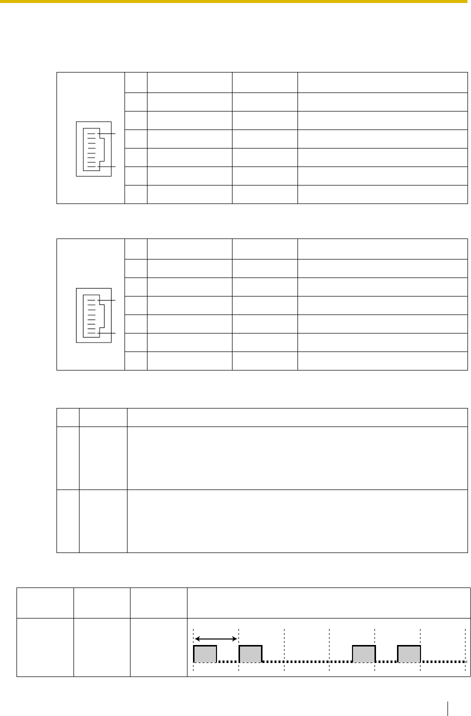
Pin Assignments
RJ45 Connector for Trunk Use
RJ45 Connector for Extension Use
LED Indications
LINE LED Flash Pattern
No. Signal Name Level [V] Function
1-2 Reserved ––
3 TX1 (+) Transmit data 1
4 RX2 (+) Receive data 2
5 RX1 (-) Receive data 1
6 TX2 (-) Transmit data 2
7-8 Reserved ––
No. Signal Name Level [V] Function
1-2 Reserved ––
3 RX2 (+) Receive data 2
4 TX1 (+) Transmit data 1
5 TX2 (-) Transmit data 2
6 RX1 (-) Receive data 1
7-8 Reserved ––
Colour Description
1 Green LINE 1 status indication
• OFF: L1 asynchronous
• ON: Synchoronous/L2 link established/clock slave
• Flash: Refer to "LINE LED Flash Pattern" below for details.
2 Green LINE 2 status indication
• OFF: L1 asynchronous
• ON: Synchoronous/L2 link established/clock slave
• Flash: Refer to "LINE LED Flash Pattern" below for details.
L1 L2 Master
Clock
Flash Pattern
ON OFF OFF
8
1
8
1
1 s


