


Connect the IP Phone 2004 components
14
Connect the IP Phone 2004 components
Before you begin
Steps
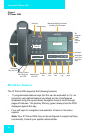
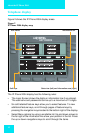
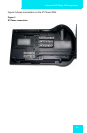
1. Connect one end of the handset cord to the handset jack (identified
with a handset icon) on the back of the telephone. Connect the other
end to the jack on the handset (see Figure 3 on page 15).
2. Choose one of the following connections:
a. For a telephone not sharing LAN access with a PC, connect one
end of the CAT5 line cable to the LAN Ethernet port located on
the back of the telephone (identified with a LAN icon). Plug the
other end of the CAT5 line cable into the IP network.
b. For a telephone sharing LAN access with a PC, connect one end
of the CAT5 line cable to the LAN Ethernet port located on the
back of the telephone (identified with a LAN icon) and the other
end to the IP network. Insert a second CAT5 line cable into the
PC Ethernet port located on the back of the telephone (identified
with a PC icon) and the other end into the computer’s Ethernet
port.
3. Contact your installation technician for the proper power option. This
telephone can be powered by an AC adapter or over a LAN.
4. Thread the cord around the strain relief, retaining hook and channel
provided for a secure power connection.
5. Secure the telephone footstand to the telephone base. Use the angle
grip on the top back of the telephone to change position.
CAUTION
Damage to Equipment
Do not plug the IP Phone 2004 into a regular
telephone jack. This results in severe damage
to the IP Phone 2004. Consult your system
administrator to ensure that you plug your
telephone into a 10/100BaseT Ethernet jack.