


IR System
Compatible with virtually all brands
of remotes using carrier frequencies
between 18 and 100kHz. As of this
publication date, the only known
components using carrier frequen-
cies outside this range are Bang &
Olufsen components and 1996
model year Pioneer receivers using
the ISC remote control (e.g. VSX-
D704S).
Wiring Requirements
Individual home-runs of 2 conduc-
tor shielded cable from each sen-
sor/keypad, West Penn D291 or
equivalent
Unit Dimensions
5” wide x 2” high x 4 1/8” deep
Power Requirements
12v DC 800 mA power supply
(included).
Niles Audio Corporation 12331 S.W. 130 Street Miami, Florida 33186 Tel: (305) 238-4373 Fax: (305) 238-0185
©1999 Niles Audio Corporation. All rights reserved. Because Niles constantly strives to improve the quality of its products, Niles reserves the right to
change product specifications without notice. Niles, the Niles logo, IntelliPad and Blending High Fidelity and Architecture are registered trademarks of
Niles Audio Corporation. Decora is a registered trademark of Leviton Manufacturing Company. Printed in USA 11/95 DS00157A
Specifications
®
Proper Power Supply
You must connect a Niles 12v DC
wall adapter (Niles XF00019) into
the switched AC power outlet of the
preamp/receiver in your system.
Any 12v DC power supply with a
minimum of 100mA current capaci-
ty can be substituted.
Extending the Cable
If you must extend the cable from
the wall adapter to the IRP6+’s sta-
tus input jack be sure to maintain
correct polarity. The tip of the plug
should be positive (+) and the
sleeve negative (-). Any 16 gauge 2-
conductor cable can be used to
extend the power status cable up to
200 feet.
Checking the Power Supply
It is possible to check the status
power supply itself and any connec-
tions that were made to extend the
cable by inserting the status plug
into the Power jack on the IRP6+. If
the Power LED lights the status
power supply and connections are
OK. If the Power LED does not light
check all connections and replace
the power supply if necessary. For
more details on incorporating the
IntelliPad please refer to the
IntelliPad’s users manual.
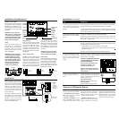
Power Status—Installation Considerations
CONVERTING A LOW VOLTAGE CONTROL OUTPUT TO 12V DC
Many components, particularly surround processors and digital preampli-
fiers, provide a low voltage whenever the component is “on” rather than
in “standby”. For the IRP6+ to correctly broadcast power status you must
install an optional Niles OTI-512 Opto-Isolated trigger interface. The OTI-
512 will convert 3-30 volts AC or DC to 12v DC.
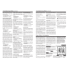
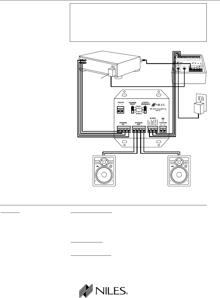
DC Power
Supply Plugged
into a Switched
Outlet
Stereo Receiver
IR Flasher
IRP6+
Rear Panel
of the
IntelliPad
Loudspeaker Loudspeaker
DC Power
Supply
Plugged into
an Unswitched
AC Outlet
Figure 7
IntelliPad Basic Configuration
utilizing Status Feedback and
Speaker Relay Features
www.nilesaudio.com