


10) Replace the IRP6+
If you have another IRP6+, replace
the one in the system and retest, if
not go to Step 11.
11) Replace the Sensor or Keypad
If you have another Sensor or
Keypad, exchange it and retest the
system, otherwise return the IRP6+
and the sensor/keypad(s) to your
local Niles dealer for testing.
12) System suddenly seems to be
OK again.
The connections were poor and by
touching and inspecting them you
have changed their condition. Jiggle
and tug on the wires and recheck the
connections. If they all seem secure,
retest the entire system per the
Troubleshooting Guidelines.
13) IR LED without any IR input.
Observe the green IR Test LED on the
IRP6+ with the power supply
plugged in and all sensors and flash-
ers connected.
• IR Test LED is On or is Flickering:
Go to Step 32
• IR Test LED is Off: Go to Step 14
14) IR LED with IR input.
Have someone watch the green IR
LED on the IRP6+ while you aim a
remote control at a remote sensor
and press a button.
• IR Test LED Flashes: Go to Step 15
• IR Test LED Off: Go to Step 23
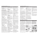
15) Flasher Connections
Verify the polarity of the flasher con-
nections. Flashers must be connected
according to Installation Steps 4
and 5. Examine the connectors for a
ny hair-like filaments of wire between
any of the contacts. Retest the sys-
tem per the steps outlined in the pre-
vious section titled Testing the IR
System
• Good Operation: Congratulations!
• Poor Operation: Go to Step 16
16) Flasher Output Too High
Some audio/video component’s
sensors are overloaded by too
strong a command from the
flasher. Connect the flasher(s) to the
variable output of the IRP6+ and use
a 1/8” slotted screwdriver to reduce
the output level to minimum
(counter-clockwise). Retest the sys-
tem per the steps outlined in the pre-
vious section titled Testing the IR
System
• Poor Operation: Move the flasher
so that it is farther away from
the sensor window or off to the
side of the sensor window.
Retest the system.
• Poor Operation: Start raising the
level (a quarter turn clockwise each
time) and retesting until level is
back to full.
• Poor Operation Continues: Go to
Step 17
17) Test Flashers.
A) If you have only ONE FLASHER,
reconnect it to the other flasher out-
put. Retest the system according to
the guidelines on page 11.
• Good Operation: Congratulations!
• Poor Operation: Go to Step 19
B) If you have MORE THAN ONE
FLASHER, disconnect all of them and
reconnect one flasher at a time. Test
for improved operation. Continue
testing until you have identified the
defective flasher. Test all of your
flashers.
• Allflashers appear defective:
Go toStep18
• One flasher doesn’t work: Return
the defective flasher to your dealer
• All flashers now work:
Congratulations!
18) Test Flasher Outputs
Reconnect one flasher to the second
flasher output of the IRP6+. Test for
improved operation. Repeat Step 16
(adjust flasher level and position).
Test for improved operation.
• Good Operation: Congratulations!
• Poor Operation: Repeat this step
with another flasher. Retest.
• Poor Operation Continues: Go to
Step 19
19) Sensors in the Same Room as a
Flasher?
• If you have sensors in the same
room as a flasher: Go to Step 20
• If all sensors are in remote loca-
tions without flashers : Go to
Step 21
• If you have keypads only: Go to
Step 21
20) Optical Feedback Loop
If there is an IR sensor and an IR
flasher located within the same room
an "optical IR feedback loop" can
occur. Replace the IRC-1 Flooding
Flasher with an IRC-2 MicroFlasher
on the front panel sensor window of
each component. Place the enclosed
IR blocking cover over each of the
IRC-2 flashers. Retest the system.
• Good Operation: Congratulations!
• Poor Operation: Go to Step 16
(adjust Flasher Level and Position)
Retest system.
• Still Poor Operation: Go to Step
21
21) Replace IRP6+ and Flasher(s)
Reconnect the system with a new
IRP6+ and new flasher(s).
• Poor Operation Continues: Go to
Step 22
22) Interference that Does Not
Light the IR Test LED
Some very rare examples of interfer-
ence (both optical and electromag-
netic) do not light up the IR test LED
but do prevent proper operation. Go
to steps 36 and 37. Examine your
installation carefully for a source of
low-level optical or electromagnetic
interference.
23) Disconnect All Sensors and
Keypads and Test One Sensor Input
Disconnect all Sensors and Keypads.
Reconnect one of the sensor cables
and retest the system (Have some-
one watch the green IR LED on the
IRP6+ while you aim a remote con-
trol at a remote sensor and press a
button).
• IR Test LED Flashes: Go to Step 24
• IR Test LED Off: Go to Step 25
24) Test Second Sensor Input
A) If you DO NOT have a second
sensor/ Keypad, Go to Step 25.
B) If you DO have another
sensor/keypad, connect it to the sec-
ond sensor input. Retest the system
Troubleshooting Guide continued
There are four basic problems which
prevent proper operation of your
IRP6+. In the order of probability, the
problems are as follows:
Bad Connections or Wiring
If the connections or wiring are
wrong, loose, shorted or open the
system will not operate properly. The
symptoms could include: Power LED
flickers or is off, IR Test LED is contin-
uously flickering or on without any
remote control use, intermittent
operation or no operation.
Steps (3) and(4) test your power
supply connections.
Steps (13) thru (14), (23) thru (25)
test your Sensor connections.
Steps (15) thru (18) test your Flasher
connections.
Steps (26) and (27) tests your cable
for shorts and opens.
Flasher Level is Too High
Many audio/video component’s
sensors are overloaded by receiv-
ing too strong of an IR command
from the flasher. Symptoms can
include: popping and clicking
sounds from the speakers when a
button is pressed on the remote con-
trol, poor IR receiving range, inter-
mittent operation or no operation.
Step (15) provides detailed instruc-
tions on setting the proper flasher
level.
Optical or Electromagnetic
Interference
Sunlight, reflections, neon signs and
other sources of infrared light or tele-
vision sets, light dimming controls
and other sources of electromagnetic
fields can induce noise and interfer-
ence into your IR extender system.
Symptoms can include: flashback
LED’s continuously flickering or on
without any remote control use,
poor range, intermittent operation or
no operation.
Steps (32) through (38) trou-
bleshoot interference problems.
Optical Feedback Loop
If you have an IR sensor in the same
room as a flasher, and you have
some low-level noise or interference,
an optical feedback loop can occur
which will interfere with proper oper-
ation. Symptoms can include: poor
range, intermittent operation or no
operation.
Steps (19)through (22) provide
instructions for eliminating optical
feedback loops.
Start from Step One
In your installation you may be faced
with a combination of the four prob-
lems or symptoms that are universal
to all of the problems. Rather than
trying to guess which problem you
have, use a process of elimination.
The Troubleshooting section is
designed to eliminate the most com-
mon problems first. If you start from
Step 1 and methodically check every-
thing you will find the problem in
much less time than the trou-
bleshooter who makes assumptions.
Troubleshooting Guidelines
1) Test Remote Control
Verify that the remote control works
by operating the equipment directly.
If the remote does not operate your
system directly, replace the batteries
of the remote control. Replace the
remote control if necessary.
2) Flasher Positioning
Flashers operate line-of-sight; be sure
they are unobstructed and aimed at
the front panel sensor windows of
your components.
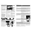
3) 12v DC Power Supply
Test that the red IRP6+ power LED is
on when the wall adapter is plugged
into an unswitched AC outlet.
• Power LED On: Go to Step 13
• Power LED Off: Go to Step 4
4) Disconnect Sensors
If the power LED does not light, dis-
connect all sensors and retest the
power supply.
• Power LED On: Go to Step 6
• Power LED Off: Go to Step 5
5) Replace Power Supply
Either your power supply or your
IRP6+ is defective. If you have anoth-
er 12v DC power supply, first check
that it has the same polarity (+ on
the tip, GND on the sleeve). Plug the
new power supply in and observe
the Power LED.
• Power LED On: Retest System per
Testing the IR System section on
previous page
• Power LED Off: Return IRP6+ to
your local Niles dealer for testing
6) Test Sensor Input 1
Reconnect one of the sensor cables.
Re-test; plug the power supply back
in and observe the Power LED.
• Power LED On: Go to Step 7
• Power LED Off: Go to Step 8
7) Test Sensor Input 2
A) If you DO NOT have a second
sensor/keypad, Go to Step 12.
B) If you DO have another sensor/
keypad, connect it to the second
sensor input and re-test.
• Power LED On: Go to Step 12
• Power LED Off: Go to Step 8
8) Short between +12v (positive)
and GND (ground).
Examine the connectors for a hair-
like filament of wire between any of
the contacts at the IRP6+ and at the
sensor or keypad.Then retest.
• Power LED On: Go to Step 12
• Power LED Off: Go to Step 9
9) Test the Cable for Shorts
Disconnect the cable at both ends
(at the sensor and at the IRP6+) and
test it for shorts. Use an ohm meter
or electrical continuity checker. You
should read an open (Infinite Ohms)
between Red and Bare, Red and
Black or Bare and Black.
• Short in Cable: Replace cable
• Cable tests OK: Go to Step 10
Troubleshooting Guide