


ND-45503 (E) CHAPTER 2
Page 21
Revision 2.0
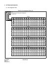
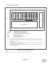
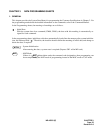
4.3 Bay Face Layout for Cards
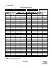
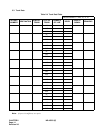
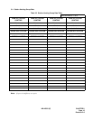
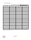
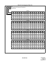
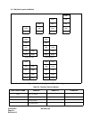
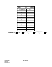
Figure 2-2 Circuit Card Mounting Slots
Note: For the details of mounting condition, refer to Circuit Card Manual.
BUILT-IN BATTERY
PIM
0-7
LT00
LT01
LT02
LT03
LT04
LT05
LT06
LT07
LT08
LT09
LT10/AP0
LT11/AP1
LT12/AP2
LT13/AP3
LT14/AP4
LT15/AP5
FP/AP6
MP/FP/AP7
BUS/AP8
*1
PWR
*2 *3 *4
LT00-LT15: Line/trunk circuit card mounting slots
AP0-AP8: Application circuit card mounting slots
MP: PN-CP00/PN-CP00-B/PN-CP03 mounting slot
FP: PN-CP01 mounting slots
BUS: PN-BS00/PN-BS01 mounting slot
PWR: PZ-PW86 mounting slot
*1
Either line/trunk circuit cards or application circuit cards can be mounted in these slots.
*2
PN-CP01 or an application circuit card is to be mounted in this slot according to the system
configuration.
*3
PN-CP00
/
PN-CP03, PN-CP01 or an application circuit card is to be mounted in this slot
according to the system configuration.
*4
PN-BS00, PN-BS01 or an application circuit card is to be mounted in this slot according to
the system configuration.