


TK-2160
3
OPERATING FEATURES
1. Operation Features
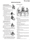
Installing the (Optional) Antenna
Screw the antenna into the connector on
the top of the transceiver by holding the
antenna at its base and turning it clockwise
until secure.
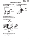
Installing the Belt Clip
Note: When first installing the belt clip, you must remove the
battery pack from the rear of the transceiver.
1 Remove the two screws from the
rear of the transceiver, then remove
the small, plastic black covering that
was held in place.
2 Insert the belt clip mount into the
space on the rear of the transceiver.
3 Using the 2 screws, affix the belt
clip in place.
Note: Do not dispose of the plastic
black covering! If you remove
the belt clip, replace the covering
into the space on the rear of the
transceiver. Either this covering
or the belt clip must be in place,
otherwise the battery pack may
not remain installed properly.
Installing the Cover over the
Speaker/ Microphone Jacks
Note: When installing the speaker/
microphone jack cover, you must
remove the battery pack from the
rear of the transceiver.
If you are not using a speaker/
microphone, install the cover over the
speaker/ microphone jacks using the
supplied screw.
Note: To lift the cover after it has been installed, use a piece
of hardened plastic or metal, such as a small screwdriver.
Lift the cover by its tab, beside the screwhole, taking
care not to damage the cover.
Installing the (Optional) Speaker/ Microphone
Note: When installing the optional
speaker/ microphone and its
locking bracket, you must
remove the battery pack from
the rear of the transceiver.
1 Insert the speaker/ microphone
plugs into the speaker/ microphone
jacks.
2 Attach the locking bracket using the supplied screw.
Note: To lift the locking bracket after it has been installed,
use a piece of hardened plastic or metal, such as a small
screwdriver. Lift the bracket by its tab, beside the
screwhole, taking care not to damage the bracket.
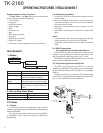
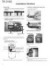
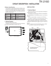
GETTING ACQUAINTED
The transceiver is shown with the optional KNB-24L battery
pack.
qq
qq
q LED indicator
Lights red while transmitting. Lights green while receiving.
Flashes orange while receiving a 2-Tone, DTMF, or
FleetSync signal that matches the one set up in your
transceiver. If programmed by your dealer, flashes red when
the battery power is low while transmitting.
w Channel Switch
Rotate to select a channel from 1 to 16.
e Power switch/ Volume control
Turn clockwise to switch ON the transceiver. Rotate to
adjust the volume. To switch OFF the transceiver, turn
counterclockwise fully.
r AUX key
This is a PF (Programmable Function) key. Press it to activate
its auxiliary function (page 4). The default setting for this
key is None.
t PTT (Push-to-Talk) switch
Press this switch, then speak into the microphone to call a
station.
y Side 1 key
This is a PF (Programmable Function) key. Press it to activate
its auxiliary function (page 4). The default setting for this
key is None.
u Side 2 key
This is a PF (Programmable Function) key. Press it to activate
its auxiliary function (page 4). The default setting for this
key is Squelch Off Momentary. Press each key to activate
its auxiliary function.
i SP/MIC jacks
Connect an optional speaker/ microphone here.
Antenna
Microphone Speaker
4
1 2 3
5
8
6
7