


ADDENDUM TO ISSUE 4 OF THE AXXESS MANUAL OCTOBER 1997
Page 67 of 73
CHANGES AND CORRECTIONS TO
THE ISSUE 4 AXXESS MANUAL
Please note the following changes and corrections to
Issue 4 of the manual.
Various locations throughout the manual: Japanese
prompts can be viewed only on “digital” display key-
sets. Analog keysets do not support Japanese displays.
Page xx, step 1: Add the following to the list of FCC
registration numbers: BE2USA–24359–PF–E.
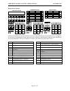
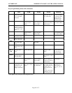
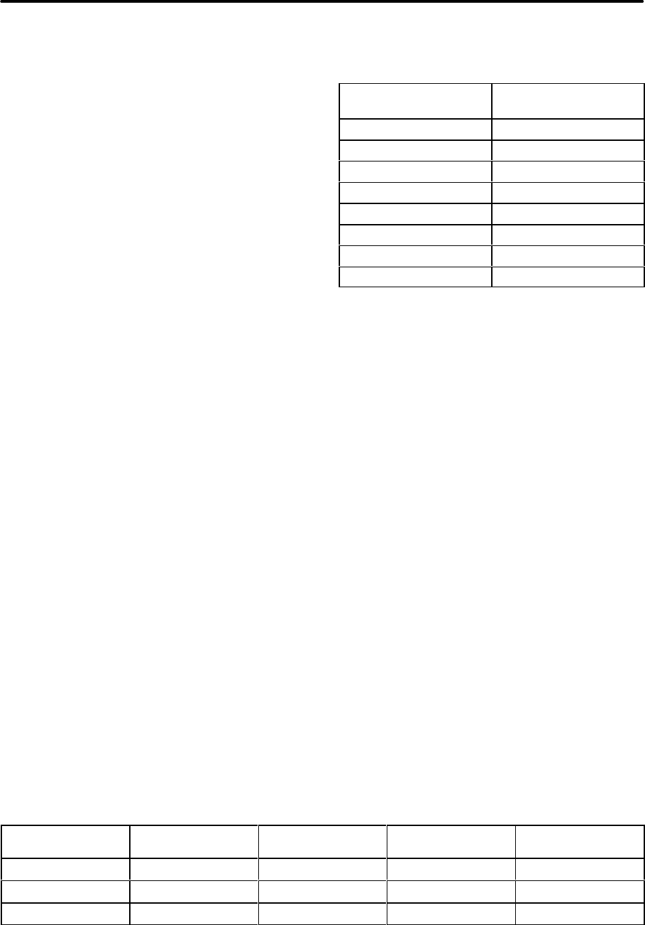
Page xxi: The FCC chart at the top of the page should
contain the changes/additions shown in the chart at the
bottom of this page.
Page xxii: The AXXESS system is now product safety
certified by Canadian Standards Association (CSA) for
use in both the United States and Canada.
Page 1–9: The maximum number of AXXESSORY
Consoles that can be installed on the system (dual or
quad) is four.
Pages 2–2, 2–23, 3–74, 4–42, 4–53, and 8–2: The vol-
ume adjustment range of non-AIM and non-DVK ana-
log keysets may not be suitable in all user environ-
ments. In such cases, Inter-Tel recommends using AIM
and/or DVK keysets, if possible.
Pages 2–5, 2–19, 3–68, and 6–142: Add the following
note to these pages. NOTE: In tri-/quad-cabinet instal-
lations, the master T1C (if one exists) should be located
in the master dual-cabinet.
Page 2–6, paragraph 3.13: Some of the dimensions
listed for the new-style dual-cabinet KSU are incorrect.
The height should be 10.5 in. (26.7 cm.), the width
should be 33.0 in. (83.8 cm.), and the depth should be
11.5 in. (29.2 cm.).
Page 2–8, paragraph 3.22, NOTE: Delete “automated
attendants” from this note. Automated attendants use
the DTMF receivers on the AXXESSORY Talk Voice
Processing Card(s).
Page 2–12, paragraph 3.52, first bullet: The relay
jack information for the CPU/MEM Card should read:
The output is two normally-open (deactivated) single-
pole double-throw (SPDT) relays that are held closed
(activated) at the same time during system operation.
Page 2–14, first bullet: Add the following fiber-optic
cable specifications:
Fiber Diameter
62.5/125 (outer/inner
core in microns)
Mode Multi-mode
Wavelength 820nm
Maximum Attenuation 5db/km
Minimum Bandwidth 50MHz
Terminating Connector ST.
Pairs 1
Maximum Length 1km
B–L Product 20MHz
Page 2–14, second column, second bullet: The relay
jack information for the CPU020/PCM Card should
read: The output is one normally-open (deactivated)
double-pole double-throw (DPDT) relay (actually
wired as SPDT) that is held closed (activated) during
system operation.
Pages 2–24, 3–80, and 8–5: The original model
PCDPM (part no. 550.3014) has been replaced with a
new model (part no. 550.3018) that does not require an
external AC transformer. Refer to the revised installa-
tion instructions included with the new unit.
Pages 2–24, 3–83, and 8–5: The MDPM (part no.
550.3015) now includes an AC transformer; it no lon-
ger needs to be ordered separately.
Page 2–33, paragraph 5.2, second bullet: The second
sentence in the note following the bullet should be
changed to read: Also, for systems with 16 or more
ports, the PC Motherboard should be equipped with
16MB RAM.
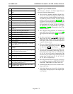
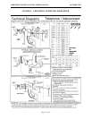
Page 2–38, paragraph 6.20: Add the following note to
the drawing. NOTE: On the CPU020/PCM Card, R1C
is wired in parallel to R2C, R1NC is wired in parallel to
R2NC, and R1NO is wired in parallel to R2NO.
Pages 3–39 and 3–45: The drawing on page 73 of this
addendum contains some additional grounding infor-
mation from DITEK. (Inter-Tel’s Factored Products
division sells DITEK surge/spike protectors.)
TYPE OF PORT
INTERFACE
FACILITY INTERFACE
CODE (FIC)
RINGER EQUIV-
ALENCE NO. (REN)
SERVICE ORDER
CODE (SOC)
USOC JACK
CONNECTOR
2-Wire Loop 02LS2 0.6B — RJ21X
2-Wire Loop/Ground 02LS2/02GS2 3.6B/4.4B — RJ21X
Primary Rate 04DU9–1SN — 6.0Y RJ48C